A Sierra Monitor Company FS-B-OPC-01 Start-up Guide APPLICABILITY & EFFECTIVITY Description FS-B-OPC Series FieldServer The instructions are effective for the above as of February 2009 Kernel Version: Document Revision: 5.
FS-B-OPC-01 Series FieldServer Start-up Guide Table of Contents TABLE OF CONTENTS 1 Pre-Installation Check List .............................................................................................................................. 3 1.1 Supplied equipment.......................................................................................................................................3 1.2 Mounting ................................................................................................
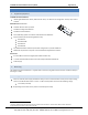
FS-B-OPC-01 Series FieldServer Start-up Guide 1 1.1 Page 3 of 10 PRE-INSTALLATION CHECK LIST Supplied equipment FS-B-OPC-01 Series FieldServer loaded with Modbus RTU driver, SMT Ethernet driver, FST OPC Server Configurator and any other drivers 1 ordered. USB Flash Drive loaded with: FS-B-OPC-01 Series Start-up Guide FieldServer Configuration Manual FieldServer Utilities Manual Driver Manual(s) specific to all Drivers ordered with the FieldServer.
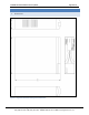
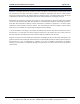
FS-B-OPC-01 Series FieldServer Start-up Guide 2 2.1 Page 4 of 10 PRODUCT DESCRIPTION Dimensions Figure 2-1: Diagram of FS-B-OPC-01 Showing External Dimensions FieldServer Technologies 1991 Tarob Court Milpitas, California 95035 USA Web:www.fieldserver.com Tel: (408) 262-2299 Fax: (408) 262-2269 Toll Free: 888-509-1970 email: support@fieldserver.
FS-B-OPC-01 Series FieldServer Start-up Guide 2.2 Page 5 of 10 Specifications Power requirements (power supply is external) FS-B-OPC-01 power supply P/N PWR-ACDC-12v-5A-60W Input voltage: 100-240Vac, 60W (max); Output voltage / current: 12Vdc @ 5.0A Physical Dimensions(excluding the external power supply) (WxDxH): 7.70 x 9.50 x 2.10 inches (19.56 x 24.13 x 5.33 cm) Weight: 2.4 lbs. (1.
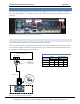
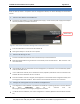
FS-B-OPC-01 Series FieldServer Start-up Guide 3 Page 6 of 10 CONNECTION TO THE DEVICE The 12VDC power supply received with the unit needs to be plugged into a power source and then connected to the back of the FieldServer. Ensure that the power supply used complies with the specifications provided in Section 2.2. Serial Power Ethernet Figure 3-1: View of back of FS-B-OPC-01 showing Connection Ports 3.1 RS-232 connection The FS-B-OPC-01 Series FieldServer is shipped with the RS-232 port activated.
FS-B-OPC-01 Series FieldServer Start-up Guide 3.2 Page 7 of 10 Ethernet Connection If connecting to a hub/switch use the provided Cat5 UTP Ethernet cable to connect the FieldServer to the hub. If connecting directly to the device, an Ethernet Crossover cable is required (not provided). Note that the front USB ports and Compact Flash port are not activated. FieldServer Technologies 1991 Tarob Court Milpitas, California 95035 USA Web:www.fieldserver.
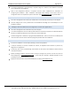
FS-B-OPC-01 Series FieldServer Start-up Guide 4 Page 8 of 10 OPERATION Read this Start-up Guide in conjunction with the Configuration Manual, the Driver Manual(s) and the Utilities manual. 4.1 Connect and Power the FieldServer. Connect the power adapter to a 100 to 240vAC power supply. Ensure that the power supply used complies with the specifications provided in Section 2.
FS-B-OPC-01 Series FieldServer Start-up Guide Page 9 of 10 If a custom configuration is not purchased, a template config.csv is loaded on the FieldServer to facilitate user configuration of the FieldServer. Refer to the Configuration Manual in conjunction with the Driver supplements for information on configuring the FieldServer. Note: FieldServer Technologies offers training on this topic as well as a configuration service to complete this portion of the work. See www.fieldserver.
FS-B-OPC-01 Series FieldServer Start-up Guide Page 10 of 10 Appendix A. Limited Warranty FieldServer Technologies warrants its products to be free from defects in workmanship or material under normal use and service for two years after date of shipment. FieldServer Technologies will repair or replace without charge any equipment found to be defective during the warranty period.