A Sierra Monitor Company Driver Manual (Supplement to the FieldServer Instruction Manual) FS-8700-64 ATMI ACM APPLICABILITY & EFFECTIVITY Effective for all systems manufactured after May 1, 2001
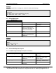
FS-8700-64 ATMI ACM Table of Contents Table of Contents 1. ATMI ACM DESCRIPTION................................................................................................................... 2 2. DRIVER SCOPE OF SUPPLY.............................................................................................................. 2 2.1 2.2 SUPPLIED BY FIELDSERVER FOR THIS DRIVER ................................................................................... 2 PROVIDED BY USER ....................
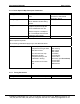
FS-8700-64 ATMI ACM Page 2 of 22 1. ATMI ACM Description The ATMI ACM driver allows the FieldServer to transfer data to and from devices over either RS-232 or RS-485 using ATMI ACM protocol. There are eight RS-232 and two RS-485 ports standard on the FieldServer. The FieldServer can emulate a passive client. ( A passive client is one that that consumes messages produced by an remote device.) 2. Driver Scope of Supply 2.
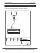
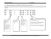
FS-8700-64 ATMI ACM Page 3 of 22 3. Hardware Connections The FieldServer is connected to the ATMI ACM Panel as shown below.
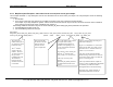
FS-8700-64 ATMI ACM Page 4 of 22 4. Configuring the FieldServer as a ATMI ACM Client The ATMI ACM driver is a passive client driver. This means that it processes unsolicited incoming data. It cannot poll for data. For a detailed discussion on FieldServer configuration, please refer to the instruction manual for the FieldServer. The information that follows describes how to expand upon the factory defaults provided in the configuration files included with the FieldServer (See “.
FS-8700-64 ATMI ACM Page 5 of 22 Example // Data Arrays // Data_Arrays Data_Array_Name, DA_AI_01, DA_AO_01, DA_DI_01, DA_DO_01, 4.
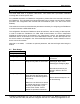
FS-8700-64 ATMI ACM Page 6 of 22 Example The following FieldServer settings are suitable for default ACM settings. // Client Side Connections Connections Port, Baud, Parity, Protocol, Handshaking, Poll_Delay P8, 9600, None, ATMI , None, 0.100s 4.3 Client Side Nodes Section Title Nodes Column Title Node_Name Function Provide name for node Node_ID ACM units do not have a node ID contained in the serial data. This field s not used in the ATMI ACM driver.
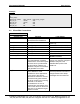
FS-8700-64 ATMI ACM Page 7 of 22 4.4.2 Driver Specific Map Descriptor Parameters Column Title Node_Name Function Name of Node to fetch data from Data_Array_Offset Position in the data array to which data should start being written. Length of Map Descriptor. The length is required to help the driver validate the CSV file. Length Address Set the length to a multiple of 16. The multiple should be the maximum area number.
FS-8700-64 ATMI ACM 4.4.4 Page 8 of 22 Map Descriptor Example 1- Gas Values, Alarms & Warnings for all slots/ports. This example illustrates the map descriptors required to complete store ACM data for 80 areas. Each map descriptor tells the ATMI ACM driver where to store each component of ACM data. The gas number & area number determine the position in the array. Read section 6.
FS-8700-64 ATMI ACM 4.4.5 Page 9 of 22 Map Descriptor Example2 – Gas values for the current (most recent) port sample. This example illustrates a map descriptors used to store the data from the most recent port sample. The map descriptor stores the following information :1. Port Number 2. Up to 16 gas values (The gas name is not provided) The position in the array is based on the Gas Number. For example. A port may sample two gasses.
FS-8700-64 ATMI ACM 4.4.6 Page 10 of 22 Map Descriptor Example3 – Storing Malfunction Data This example illustrates a map descriptor used to store malfunction data reported by the ACM unit. When a malfunction is cleared then 100 elements of the array are set to zero. When a Malfunction is present the 1st element contains the malfunction’s major type, the 2nd element contains the minor type and element x (x=major*10+minor) is set to a value of 1. Additional information is provided in section 6.
FS-8700-64 ATMI ACM 4.4.7 Page 11 of 22 Map Descriptor Example4 – Gas values for the current (most recent) slot sample. This example illustrates a map descriptors used to store the data from the most recent slot sample. The map descriptor stores the following information :5. Slot Number 6. Up to 16 gas values (The gas name is not provided) The position in the array is based on the Gas Number. For example. A slot may sample two gasses.
FS-8700-64 ATMI ACM Page 12 of 22 5. Configuring the FieldServer as a ATMI ACM Server The ATMI ACM driver cannot be used as a server. 6. Driver Notes 6.1 Data position in the Data Arrays To understand how the driver stores data for the current port, read the notes provided with mapdescriptor example 2 as the following notes do not apply. To understand how the driver stores data for malfunctions, read the notes provided with mapdescriptor example 3 as the following notes do not apply.
FS-8700-64 ATMI ACM 6.2 Page 13 of 22 Driver Stats The ATMI ACM Driver counts all incoming bytes as the ‘PLC Byte Received’ statistic. This can be viewed on the connection detail and overview screen. Typically this count will increase by approx 2500 bytes per full screen of area data. IN addition the driver reports one count of ‘PLC READ MSG RECD’ statistic for each map descriptor used to store information from a complete message.
FS-8700-64 ATMI ACM Page 14 of 22 The driver stores the following data.
FS-8700-64 ATMI ACM 17 ATMI_STAT_STORE_NO_MAP 18 ATMI_STAT_STORE 19 ATMI_STAT_STORE_NONZERO 20 ATMI_STAT_MALFN_BAD_MAJOR 21 ATMI_STAT_MALFN_BAD_MINOR 22 ATMI_STAT_MALFN_STREAMING 6.4 Page 15 of 22 When processing the most recent message, no map descriptors were found to tell the driver how to store the incoming data. Increment’s once for each time data is stored. Ie will increase by 5 for one screen full of data stored using 5 map descriptors.
FS-8700-64 ATMI ACM Page 16 of 22 ATMI:#3 Error. Incoming data on port=%d is being abandoned. MapDesc rqd. No map descriptors were found on the indicated port with which the driver could store the incoming data. Change the CSV file and reset the FieldServer. This message is only printed once even if the error occurs more than once. ATMI:#6 FYI. The mapDesc called <%s> is too short. Edit the CSV file. Increase the length of the map desc and reset the FieldServer. ATMI:#5 FYI.
FS-8700-64 ATMI ACM 6.5 Page 17 of 22 Timeouts See section 4.2 for information on how timeouts should be specified. Occasional timeouts may be expected when there are noisy messages or if the ACM device has been locked. Timeouts do not stop the driver processing the next valid screen of data. 6.6 Demand & Lock Scan The driver can process data from demand and locked scans. Incoming data is processed in the same way as normal scans and stored using the same map descriptors. 6.
FS-8700-64 ATMI ACM Page 18 of 22 Malfunction Major Type 1. INADEQUATE BYPASS FLOW 2. EMERGENCY SWITCH CLOSURE Mafunction Minor Type 0. 3. FAILED LEAK CHECK 4. DSP FAILURE in module 5. FAILURE to get interferogram 0. 0. 1.TEMP_LOW 2. TEMP_HIGH 3. LOSS_OF_NH3_FLOW 1. Bench timeout 2. Bench short scan 3. Zero ZPD value or address 4. Bench reports Bad Scan 5. Bench DREQ stuck TRUE 6. Energy (ZPD) address out of range 7. energy (ZPD) value too high 8. energy (ZPD) value too low 9.
FS-8700-64 ATMI ACM Page 19 of 22 When you use a “…-alarm” keyword then the driver stores a 1 when the gas is in an alarm condition and a zero when it is not in alarm condition. This means a zero is stored even if the gas in a warning condition. When you use a “…-warning” keyword then the driver stores a 1 when the gas is in a warning condition and a zero when it is not in warning condition. This means a zero is stored even if the gas in an alarm condition as well as when the gas is in a normal condition.
FS-8700-64 ATMI ACM Page 20 of 22 7. Revision Control Date Rev 1.01a Rev1 Resp PMC 1.01a Rev 2 PMC Description This revision and all previous revisions did not have a revision control section. This issue of the manual corresponds to the release of driver version 1.01a in which functionality was added to store the current port sample’s data separately. The following sections of this manual have been amended. • • • • • • 1.01b Rev 0 101c Rev0 102a Rev0 Section 1. client /server. Section 4.4.
FS-8700-64 ATMI ACM Page 21 of 22 10Feb03 1.03a Rev 0 PMC 9Apr03 1.04aRev 0 DNC 10Apr03 1.04aRev1 DNC Section 4.4.2 New keywords. Added slot-values and portvalues (as synonym for gas-values) Section 6.1 Calculation of Data Array offsets Section 7 Consolidated the revision information into a table. TOC Updated Table of Contents Section 4.4.2 Added new key word "Current-Slot" Section 4.4.7 Added Current-Slot example Section 6.10 Added section discussing current slot information Section 6.