
User Guide


FS-8700-31 Siemens TIWAY I Page 10 of 23
FieldServer Technologies 1991 Tarob Court Milpitas, California 95035 USA Web:www.fieldserver.com
Tel: (408) 262-2299 Fax: (408) 262-9042 Toll_Free: 888-509-1970 email: support@fieldserver.com
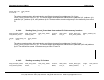
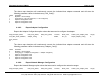
The above map descriptor will continuously read the three status values from PLC_01. The status values are
defined as follows and will be stored in the data array contiguously from an offset of zero:
Status element 1 (DD) : Operational Status
Status element 2 (EE) : Auxiliary power source status
Status element 3 (FF) : NIM Operational Status
Please refer to the TIWAY systems manual for operational values and their meanings.
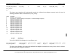
4.4.5. Writing TIWAY data map descriptor examples
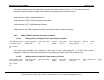
4.4.5.1. Writing data to contiguous PLC data memory locations
Map_Descriptor_Name, Data_Array_Name, Data_Array_Offset, Function, Node_name, TIWAY_Data_Type, Address, Length,
C12_RAW8_PLC07, RAW8_Data, 20, WRBC, PLC_07, Control_Register, 0, 10,
Scan_Interval
0s
The above map descriptor will continuously write data of type “Control_Register” to 10 PLC data memory
addresses. The data to write will be collected from the data array “RAW8_Data” from an offset of 20.
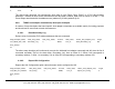
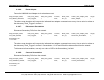
4.4.5.2. Writing data to random PLC data memory locations
Map_Descriptor_Name, Data_Array_Name, Data_Array_Offset, Function, Node_name, TIWAY_Data_Type, TIWAY_Address_List, Length,
C17_FLOAT_PLC254, FLOAT_Data, 0, WRBC, PLC_254, Loop_Gain, 5 9, 2,
Scan_Interval
0s