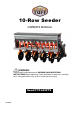
0-Row Seeder OWNER’S MANUAL WARNING: Read carefully and understand all ASSEMBLY AND OPERATION INSTRUCTIONS before operating. Failure to follow the safety rules and other basic safety precautions may result in serious personal injury.
Thank you very much for choosing this product! For future reference, please complete the owner’s record below: Model: FTF-603PTS Purchase Date: _______________ Save the receipt, warranty and these instructions. It is important that you read the entire manual to become familiar with this product before you begin using it. This product is designed for certain applications only. The manufacturer cannot be responsible for issues arising from modification.
WORK AREA • Keep work area clean, free of clutter and well lit. Cluttered and dark work areas can cause accidents. • Keep children and bystanders away while operating a seeder. Distractions can cause you to lose control, so visitors should remain at a safe distance from the work area. • Be alert of your surroundings. Using a seeder in confined work areas may put you dangerously close to cutting tools and rotating parts.
SAFETY PRECAUTIONS AND OPERATION RULES 1. 2. 3. 4. 5. 6. 7. 8. 9. 10. 11. 12. 13. Note the following in order to avoid fertilizer burn: a. The fertilizing rate should be controlled according to your field condition. b. Choose the proper fertilizer for the seed. Always inspect, maintain or adjust the seeder after each use. While operating the seeder, keep area clean, free of clutter and well lit. Keep children and bystanders away.
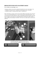
SEEDING/FERTILIZING ADJUSTMENT DEVICE (Pre-installed under the top hopper case) The seeding adjustment device is mainly composed of the seeding/fertilizing device, seeding/fertilizing box and the seeding/fertilizing wheels. The Seeding/Fertilizing Box is attached on the Seeding/Fertilizing Axis by two clips and the seed rate is adjustable by controlling the position of this seed/fertilizer wheel.
SEEDING/FERTILIZING RATE ADJUSTMENT HANDLE (Pre-installed on the top hopper case) To adjust the fertilizer rate, you will need to adjust hand wheels (on each side of hopper). The seed/fertilize rate depends on the seed/fertilizer you want to plant, please refer to your seed/fertilizer supplier’s instruction to get the proper seed/fertilize rate.
Before you adjust the hand wheel, loosen the butterfly nut first, and then pull out the plastic hold plate. Rotate the hand wheel to meet the seeding/fertilizing rate you require. After you have adjusted the seeding/fertilizing rate, insert the plastic hold plate then tighten the butterfly nut to lock the seeding/fertilizing rate. SEEDING/FERTILIZING RATE CHART Set Number Wheat Oats Rye Perennial Grass Annual Grass 1 2 3 4 5 6 7 8 9.6 9.00 11.00 17.50 16.50 20.00 25.30 24.00 29.00 33.00 31.
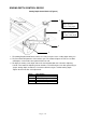
SOWING DEPTH CONTROL DEVICE Sowing Depth Control Device (Figure 4) 1 Move upward to raise sowing depth 2 Move downward to reduce sowing depth 4 3 1. The Sowing Depth Control Device makes the seeder keep the same seeding depth during use. 2. The Rear Roller will power the chain and the gear. The coulter will open the soil, the seed box will drop the seed and the cover plate will close the soil. 3. To adjust the sowing seeds depth, loosen the nut located below each side of the Adjusting Handle.
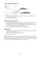
SOIL COVER PLATE (Figure 5) Spring Kit Cover Plate 1. The soil cover plate is located at the end of the seeder. There are 2 sets of springs on each plate that add down pressure. 2. This can be removed if not needed. Adjustment Before Each Use 1. Adjust the sowing depth and level of the Seeder by using the 3-point link top on your tractor. 2. Adjust coulters by loosening the u-bolts mounted on the planter main frame. Make sure distance between each opener is the same.
Trouble Shooting and Solutions 1. Close mechanism disc does not rotate: Clean, lubricate or change the disc. 2. Sowing depth not even: a. Main Frame not level: Adjust the 3-point link. b. Rear wheel not level: Adjust the handle on each side. 3. Coulters not working: a. Tractor tire mark doesn’t cover: Add the close mechanism (optional) and adjust properly. b. Rear roller not working properly: Adjust the height of rear roller to a proper height. 4.
PARTS DIAGRAMS Product comes fully assembled and this diagram is for maintenance and spare parts replacement only! Due to continuous improvement, product may differ/look different then diagram shows.
PARTS LIST Part# Description Qty. 1 Top Hopper Case 1 2 1 7 Bottom Frame Case Coulter Set Section A Rear Step Set Section B Top Gear Shield Kit Section C Bottom Gear Shield Kit Section D Plastic Funnel 8 Hose 20 9 Top Chain 2 10 Bottom Chain 2 11 Cotter Pin 40 3 4 5 6 10 1 2 2 20 Exploded Parts Diagram Section A Part# Page 12of 14 Description Qty.
Exploded Parts Diagram Section B Part# Description Qty. 17 Step Plate 1 18 Bolt 4 19 Flat Washer 8 20 Spring Washer 4 21 Nut 4 Exploded Parts Diagram Section C Part# Page 13of 14 Description Qty.
Exploded Parts Diagram Section D Part# Description 28 Shield A 2 29 Shield B 2 30 Small Nut Small Spring Washer Small Flat Washer Small Bolt 8 Large Nut Large Spring Washer Large Flat Washer Large Bolt 4 31 32 33 34 35 36 37 For replacement parts and technical questions, please call 1-218-943-6296. WARRANTY One-year limited parts warranty TG PO BOX 203 Miltona, MN 56354 Page 14of 14 Qty.