
Specification


10
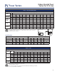
PV
Co-venting: Use CK-20FV/FG
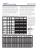
How PV Series Venters Work
MG-1
CK-20FV/FG
(Indoor Mounted Power
Venters for Oil & Gas)
Power Venters
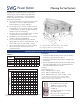
SWH
Accessories
1. Thermostat or aquastat calls for heat and starts the
Power Venter.
2. The Pressure Switch senses sufficient air flow and
allows burner(s) to start.
3. The Power Venter draws combustion air through the
system and forces gases outside through an external
Vent Hood.
4. Draft Hood or Barometric Draft Control between the
appliance(s) and the Power Venter maintains
consistent air flow.
5. After the thermostat is satisfied, the burner shuts
down and the Post Purge Control clears the venting
system of combustion gases.
6. The Power Venter shuts down.
The indoor mounted PVG and PVO Power
Venters provide an economical power venting
system for gas and oil appliances. All controls
are built into these units. A Vent Hood is required
to terminate the vent system.
SWH Vent Hoods
Designed for standard vent pipe and Class B type double-wall (B-
Vent) connection. Provides proper clearance between flue gas
stream and wall combustibles. Available in 3" through 8" sizes.
MG-1 Series Draft Control
Required for 80+ draft induced system applications. Available in
4" through 9" sizes.
CK-20FV/FG Water Heater Control
(Required for co-venting residential water heaters.)
Provides all system control components required to utilize the Field
Power Venter with natural gas or LP gas millivolt water heater,
including safety interlock controls. This kit allows you to co-vent a
residential water heater with a furnace or boiler.