
Specification


8
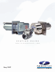
SWG
For New Installation or Upgrade of Existing SWG Systems
“Sealed Combustion System”
SYSTEM
Listed
SWG Sealed Combustion System.
B. Select the Combustion Air Tee
Select the CAT to match the Power Venter.
NOTE: Control Kits are required for operation of the SWG.
Do not exceed maximum oil GPH input.
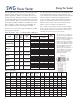
A. Size the Venter
Choose the model that matches GPH Intake.
Model Part# Description
CAT-4HD 46335601 Fits SWG-4HD, 4HDs
CAT-5 46335602 Fits SWG-5,5s
Model
Max
Oil GPH
Intake
Maximum 30 Feet of Pipe and Three
90° Elbows For Each: Intake & Exhaust
Vent Pipe Intake Pipe
SWG-4 HD
SWG-4 HDs
1.10 4" 4"
SWG-5
SWG-5s
1.85
5"
4"
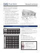
1. SWG Power Vent System
2. CK-Control Kit
3. Combustion Air Tee
4. RC Draft Control
5. Field AirBoot
®
6. VRV - Vacuum Relief Valve
7. FurnaceBoot
™
8. WMO - Safety Switch
C. Select the Control Kit
Select the Control Kit to match
the application.
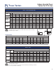
D. Select the Combustion Air System
Select the model that matches the burner.
Follow steps A through D to select the proper components for the SWG Sealed Combustion
System. If an SWG is already installed, start at step B.
Model Burner Appliance Input Components
CAS-1
Beckett AFII Burners,
Riello 40BF, NX
Up to 2 gph
4" Intake Air Hood
4" Vacuum Relief Valve
CAS-2B
CAS-2C
CAS-2W
Beckett AFG or AF Burners
Carlin EZ-1, CRD, FRD
Wayne MSR
Up to 2 gph
4" Intake Air Hood
4" Vacuum Relief Valve
Field AirBoot
®
CAS-2B90E
Beckett AFG and AF Warm Air Furnaces
Up to 1.5 gph
4" Intake Air Hood
4" Vacuum Relief Valve
FurnaceBoot
™
Model
Application & Description
CK-61
Any oil appliance / Electronic post purge
CK-62
Any oil appliance / Thermal post purge
CK-63
Any oil appliance / Electronic post purge
or operates the venter and burner motor
simultaneously w/ optional delay oil valve