
Specification


4
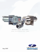
SWG
Power Venter
(Outdoor Mounted Power
Venters for Oil &
Gas)
(Sizing The Venter)
NOTE: Control Kits are required for operation of the SWG. Stainless steel recommended for oil applications.
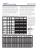
Size the SWG venter based on the input firing rate of the
appliance. If the power venter is being used to vent
multiple appliances, add the input firing rates for each
appliance and use that total to size the venter. Knowing
the total input BTU/hr. for gas, or GPH for oil, the venter
can be sized from Table 1. Select the venter rated closest
to the total input BTU or GPH for installation. If the input
of the appliance is higher than the max allowable for
that size SWG, move to the next larger size SWG.
Do not select a venter with a maximum BTU/hr. or GPH
lower than the appliance.
The equivalent feet of vent pipe for the installation must
be calculated. Based on the vent pipe diameter to be
used, compare the calculated equivalent feet of vent pipe
with the maximum equivalent feet allowable for the
venter (see Table 1). If the calculated equivalent feet is
greater than that allowed for the venter, increase the
diameter of the vent pipe to be used and refer to the
table or use the next larger size SWG venter.
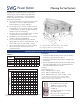
Table 2 - Specifications
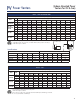
Sizing The Venter Table 1 - Use Maximum BTU or GPH Input
“s” Designates stainless steel model.
* Oil: Select venter according to the
actual rated maximum GPH input.
SWG GPH ratings at 100 psi. Do
not exceed maximum oil GPH input.
** Gas: Do not exceed maximum
BTU/hr. input rating. For multiple
venting system applications add the
input for each appliance. Category
III gas-fired draft induced systems
require an SWG-5 or larger.
Unit sizing may vary depending on
specific application. Consult your
dealer or factory representative
for the proper sizing for your
particular application.
Model Volts Hz Amps Watts RPM
Thermal
Protect.
A B C D E F
SWG-3 115 60 0.6 40 3000 YES 3" 5" 9
1
⁄16" 8
1
⁄2" 7
5
⁄8" 9
3
⁄16"
SWG-4HD 115 60 1.7 138 3000 YES 4" 6" 11
3
⁄4" 9
1
⁄2" 9" 9"
SWG-4HDs 115 60 1.7 138 3000 YES 4" 6" 11
3
⁄4" 9
1
⁄2" 11" 11
1
⁄2"
SWG-5 115 60 1.3 144 3100 YES 5" 7" 11
3
⁄4" 10
3
⁄4" 12" 12
1
⁄4"
SWG-5s 115 60 1.3 144 3100 YES 5" 7" 11
3
⁄4" 10
1
⁄2" 12" 12
1
⁄2"
SWG-6 115 60 2.1 228 3100 YES 6" 8" 11
3
⁄4" 10
3
⁄4" 12" 12
1
⁄4"
SWG-6s 115 60 2.1 228 3100 YES 6" 8" 11
3
⁄4" 10
1
⁄2" 12" 12
1
⁄2"
SWG-8 115 60 4.37 478 3100 YES 8" 10" 11
3
⁄4" 11
7
⁄8" 13" 14
1
⁄4"
SWG-10 115/230 60 11.4/5.7 1311 1725 YES 10" 14" 19
1
⁄2" 24" 20" 21"
SWG-12 115/230 60 13.6/6.8 1564 1725 YES 12" 16" 19
1
⁄2" 25" 22" 23"
SWG-14 115/230 60 14.0/7.0 1610 1725 YES 14" 18" 19
1
⁄2" 26" 24" 25"
MODEL
MAX*
OIL GPH
INPUT
100psi
MAX*
OIL GPH
INPUT
140psi
MAX**
GAS BTU/hr.
INPUT
Maximum Equivalent Feet of Vent Pipe
VENT
PIPE SIZE
AT MAX
BTU/hr. INPUT
AT 60% OF MAX
BTU/hr. INPUT
SWG-3
N/A N/A 70,000
21 80 3"
50 100 4"
SWG-4HD, 4HDs
1.10 .90 170,000
35 100 4"
65 100 5"
100 100 6"
100 100 7"
SWG-5, 5s
1.85 1.55 290,000
16 44 4"
51 100 5"
95 100 6"
100 100 7"
SWG-6, 6s
2.65 2.25 416,000
28 78 5"
68 100 6"
100 100 7"
SWG-8
4.75 4.0 740,000
26 72 7"
51 100 8"
70 100 9"
SWG-10
9 7.5 1,300,000
10 100 8"
30 100 10"
75 100 12"
SWG-12
13.5 11.5 1,900,000
16 100 10"
40 100 12"
86 100 14"
SWG-14
21 17.75 3,000,000
8 85 12"
18 100 14"
35 100 16"
Note: In Table 1, the maximum equivalent footage allowable
for the vent pipe is given for two points, the maximum BTU/hr.
venting capacity and at 60% of the maximum. This allows for
estimating values between the two given points.