
Specification


18
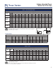
Power Venter
III. SYSTEM SETUP AND TESTING: (Continued)
6. Once proper draft is achieved, measure CO2 and smoke level. If necessary, adjust the intake airflow at
the burner to obtain the highest possible CO2 reading with a zero smoke reading. As the intake airflow
is increased or decreased, the draft may change. Repeat steps 3 through 6 to re-adjust the draft control
and choke plate before attempting any other adjustments.
7. Measure combustion efficiency and exhaust gas temperature at the venter inlet. Combustion efficiency
should be adjusted to maximum attainable at zero smoke. Exhaust gas temperature at the venter inlet
should range between 200ºF and 550ºF.
8. If maximum efficiency and zero smoke yields a temperature below 200ºF at the inlet to the venter, the
following suggestions must be considered.
A. Use a larger oil nozzle or higher oil pump pressure to raise the firing rate of the burner. Repeat
steps 3 through 7 until all combustion parameters are within the specified ranges.
B. Reduce the length of the duct from the appliance to the venter which will increase the venter
inlet temperature.
C. Insulate the vent pipe to minimize heat loss.
D. Seal the vent pipe joints to reduce uncontrolled dilution air.
Service Guide
Procedure for adjusting the pressure switch
• Turn pressure switch adjustment clockwise until the burner quits.
• Turn counter-clockwise slowly until the burner starts.
• Turn an additional 1/4 to 1/2 turn counter-clockwise.
Note: Every installation will require unique pressure switch adjustment.