
Specification


17
Power Venter
I. VISUALLY INSPECT THE GENERAL SYSTEM OPERATION:
1. The thermostat (wall thermostat, or aquastat) calls for heat, starting venter motor.
2. After the venter motor has come up to speed, the pressure switch closes. This closes the circuit to the burner and
allows the burner to operate. This occurs in approximately 1 to 2 seconds.
3. After the heating requirement is satisfied, the thermostat circuit opens and deactivates the burner and power
venter circuit.
4. Oil venting systems require a post purge device. During the post purge cycle, the venter operates for a period after
the burner has shut off. This is to purge the remaining flue gases and to cool the combustion chamber. Typical post
purge times are 3 to 5 minutes. Longer purge times may be required depending on system installation.
II. INSPECTION AND MAINTENANCE ITEMS:
1. Motor: Inspect the motor once a year, it should rotate freely. To prolong the life of the motor, lubricate with six drops of
SWG Super Lube, Part #46226200, annually. Use of any other type of lubricant may cause premature motor failure.
2. Wheel: Inspect the venter wheel annually to clear any soot, ash, or coating which inhibits either rotation or air flow.
Remove all foreign materials before operating.
3. Vent System: Inspect all vent connections annually for looseness, for evidence of corrosion, and for flue gas leakage.
Replace, seal or tighten pipe connections if necessary. Check the venter choke plate to ensure it is secured in place.
Check the barometric draft control to ensure the gate swings freely.
4. System Safety Devices: With the heating system operating, disconnect the pressure sensing tube from the pressure
switch on the CK Kit. This should stop the burner operation. Re-connecting the tube should relight the burner.
III. SYSTEM SETUP AND TESTING:
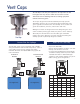
Figure 1 shows a typical oil-fired appliance and the expected ranges of several readings taken at various locations in the
system. Note: If a vent pipe reducer is required, use a smooth walled gradual reducer. Place it at the venter inlet as
shown in Figure 1.
1. Set the choke plate in the power venter, or extension kit, to its full open position. Set the draft control adjustment
weight to its midpoint position.
2. Adjust the thermostat so that the unit will run continuously. Allow the unit to operate for 5 to 10 minutes to ensure
stack temperature stabilization.
3. Find out the manufacturer’s recommended over-fire or
breeching draft. Close the choke plate on the SWG until the
draft above the draft control reads approximately 0.04” w.c.
greater than the recommended breeching draft. Example: If
the appliance manufacturer recommends a 0.02” breech
draft, adjust the choke plate to get an approximate 0.06”
draft above the draft control.
4. Adjust the barometric draft control to obtain the
manufacturer’s recommended draft over-fire or at the breech.
The draft control gate should be open approximately half its full swing during normal operation. This allows the gate
to swing open or closed depending on changes in atmospheric pressure or operating conditions.
5. If the proper draft cannot be obtained at the breech or if the gate does not open as described, then adjust the choke
plate in the SWG to reduce or increase the airflow. Re-adjust the draft control to obtain the required draft, since
moving the choke plate will change the system draft.
Service Guide
• Oil motor and fan shaft with
SWG Super Lube annually
• Works in conditions of -40° to
300° (F)
• Synthetic lubricant which
maintains specified viscosity
• Use of any other lubricant may
cause premature failure
SWG Super Lube