
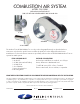
Overview of Primary Product

page 7
ADJUSTMENTS
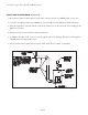
AIR INTAKE BOOT AIR SETTING
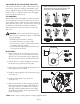
Follow the instructions in the Boiler and Burner Installation Manuals for adjusting and setting the burner.1.
WARNING: Failure to properly adjust the burner after installing this kit can result in severe personal
injury, death or substantial property damage.
Loosen the air band screw on the Air Boot™. Position the screw at the initial setting on the following 2.
chart. Use this setting only as a starting point. Do not leave the burner with this setting unless your testing
proves it to be acceptable.
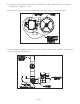
Start the burner and adjust the air control as needed to achieve the required CO3.
2
and smoke levels. Set
over fire draft to appliance manufacturer's specifications (typically -.02" of water). Secure air control knob
with indicator bracket. If draft levels are not obtainable or controllable, use standard industry methods to
control the draft or call the Field Controls Tech Line at 1-800-742-8368 for more information.
Adjust the counterweight on the vacuum relief valve so the gate remains closed during the burner setup 4.
and testing.
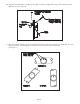
VACUUM RELIEF VALVE COUNTERWEIGHT
After you have completed adjusting the burner, adjust the VRV counterweight. 1.
With the burner running normally, rotate the counterweight screw counterclockwise until the gate just 2.
begins to open.
Check the combustion again to verify no changes have occurred. If OK, hold the counterweight screw in 3.
position and tighten the hex nut against the gate to lock the screw permanently in position.
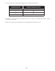
INITIAL AIR BOOT
TM
AIR CONTROL SETTINGS
Input Range (GPH) Air Band Setting
0.55 - 0.70 25º F
0.75 - 1.00 60º F
1.10 - 1.75 80º F
2.00 - 2.55 180º F