
Install Instructions

page 5
WIRING
The following requirements must be met to ensure safe and proper operation:
• The Flue Sentinel® Electronic Fireplace Damper must be electrically connected to the replace appliance using the chimney
upon which the damper is installed.
• The damper must be installed in accordance with the NEC NFPA 70 (most recent edition) and/or local codes.
• The damper must be installed using the wiring harness supplied with it. This harness has a mated connector which plugs
into the damper controller.
• The damper’s wiring harness must terminate at the gas valve.
• The wiring connecting the damper controller to the gas valve must be a minimum of 18 AWG and must be run in conduit if
installed on the exterior of the chimney or required by code.
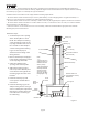
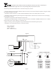
• Figure 2 is a wiring connection diagram for a typical installation with an intermittent ignition system.
• The damper control wiring must always be connected as follows:
Brown - 24 VAC Hot
Orange - Signal In
Yellow - Signal Out
Black - 24 VAC Common
WARNING: This damper device MUST be interlocked with all automatic gas valves on the replace
appliance. DO NOT negate the action of any existing safety of operational control.
FLUE
SENTINEL
ELECTRONIC
FIREPLACE
DAMPER
L1
L2
120 VAC
24 VAC
GAS VALVE
IGNITION CONTROL MODULE
SPARK ELECTRODE/
SENSOR
YELLOW
ORANGE
BROWN
BLACK
FIREPLACE
SWITCH
24V
GND
TH-W
TRANSFORMER
Figure 2
31
4
2
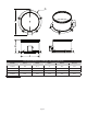
VIEW SHOWING
YELLOW3
4 BLACK
END OF RECEPTACLE
WIRE CONNECT
CODE
1
2
BROWN
ORANGE
COLOR
3
1
4
2
VIEW SHOWING
GREEN3
4 BLACK
END OF RECEPTACLE
WIRE CONNECT
CODE
1
2
WHITE
RED
COLOR
HARNESS COLOR CODE
Standard Wire Connector
High Temp Wire Connector