
Install Instructions

REMOVAL AND INSTALLATION
1. Remove the FAD replacement motor assembly from the
1. Remove the FAD replacement motor assembly from the
packaging and examine for possible shipping damage.
packaging and examine for possible shipping damage.
2. Verifying proper alignment of the wiring harness
2. Verifying proper alignment of the wiring harness
connectors on the existing motor assembly disconnect
connectors on the existing motor assembly disconnect
the wiring harness connector and strain relief connector
the wiring harness connector and strain relief connector
from the motor assembly.
from the motor assembly.
3. Carefully inspect the wiring harness connectors for
3. Carefully inspect the wiring harness connectors for
looseness, corrosion, or other damage to the terminals.
looseness, corrosion, or other damage to the terminals.
4. Verify that the damper wiring harness is properly
4. Verify that the damper wiring harness is properly
connected to the IVRC unit, following the ventCool™
connected to the IVRC unit, following the ventCool™
installation instructions.
installation instructions.
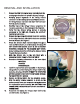
5. Remove the two screws that attach the motor assembly
5. Remove the two screws that attach the motor assembly
to the damper bracket, and remove the motor assembly
to the damper bracket, and remove the motor assembly
from the damper. (See Figure 1)
from the damper. (See Figure 1)
6. Rotate the damper shaft counterclockwise through at
6. Rotate the damper shaft counterclockwise through at
least one full revolution, to verify freedom of motion. DO
least one full revolution, to verify freedom of motion. DO
NOT ROTATE THE DAMPER SHAFT IN THE CLOCKWISE
NOT ROTATE THE DAMPER SHAFT IN THE CLOCKWISE
DIRECTION;
DIRECTION;
DAMAGE TO THE DAMPER MAY OCCUR.
DAMAGE TO THE DAMPER MAY OCCUR.
Some resistance should be felt when the damper rotates
Some resistance should be felt when the damper rotates
through the closed position.
through the closed position.
7. Mark the damper size on the unit label with a
7. Mark the damper size on the unit label with a
permanent marker. Example: “Model #: FAD-14”.
permanent marker. Example: “Model #: FAD-14”.
8. Record the following information on the cover label:
8. Record the following information on the cover label:
INSTALLER:
INSTALLER:
ADDRESS:
ADDRESS:
DATE INSTALLED:
DATE INSTALLED:
9. Install the replacement motor assembly on the damper,
9. Install the replacement motor assembly on the damper,
using caution to avoid rotating the damper shaft in the
using caution to avoid rotating the damper shaft in the
clockwise direction. DO NOT ATTEMPT TO ROTATE THE
clockwise direction. DO NOT ATTEMPT TO ROTATE THE
MOTOR ASSEMBLY SHAFT COUPLING BY HAND; DAMAGE
MOTOR ASSEMBLY SHAFT COUPLING BY HAND; DAMAGE
TO THE MOTOR WILL OCCUR!
TO THE MOTOR WILL OCCUR!
10. Replace and rmly tighten the two attaching screws.
10. Replace and rmly tighten the two attaching screws.
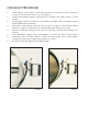
11. Align the wiring harness connector as shown on the
11. Align the wiring harness connector as shown on the
motor assembly cover, and connect the wiring harness to
motor assembly cover, and connect the wiring harness to
the replacement motor assembly. DO NOT FORCE THE
the replacement motor assembly. DO NOT FORCE THE
CONNECTION; A MISMATCH MAY CAUSE A HAZARDOUS
CONNECTION; A MISMATCH MAY CAUSE A HAZARDOUS
CONNECTION!
CONNECTION!
12. Reconnect and tighten the harness strain relief to the
12. Reconnect and tighten the harness strain relief to the
conduit bracket. (See Figure 1)
conduit bracket. (See Figure 1)
FIGURE 1
FIGURE 2