
User Guide


page 2 of 8
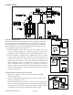
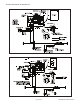
MOUNTING CONTROL BOX
The control box must be mounted within 6' of the vent damper, and within
reach of the appliance's existing damper cable. If the control box must be
mounted out of reach of the power venter's attached wiring, an additional
installer supplied junction box and wiring (with approved wiring enclosure
if necessary) will be required. (See Figure 1 & 2)
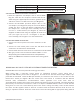
1. Install the exible conduit connector onto the CK-92FVP control box
and secure with fastening nut. If additional wiring is required, install
the exible conduit connector onto the installer supplied junction box.
2. Fasten the exible conduit from the SWG Venter into the conduit
connector. Mount the CK-92FVP control box onto a non-heated vertical
surface of the appliance or nearby wall or oor joist through the four
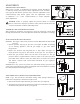
dimpled locations on the base of the box. NOTE: The mounted pressure
switch diaphragm must be mounted with a vertical orientation; see
label on pressure switch. (See Figure 3) If required, run additional
wiring as in gure 2 and connect to CK-92FVP control box, if required,
using the supplied exible conduit connector and approved connectors
and anti-short bushings.
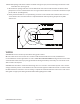
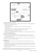
PRESSURE SWITCH SENSING TUBE INSTALLATION
1. Attach the
1
⁄4" tubing connector to the pressure tube on the SWG
Venter. (See Figure 3)
2. Connect installer supplied
1
⁄4" OD aluminum, copper or stainless steel
tubing to the tubing connector.
3. Route the tubing to the CK control box and connect the tubing to the
pressure switch using supplied plastic nut. When routing the tubing,
avoid kinking the tubing by bending the tubing too sharply. Support
the tubing at 2' intervals using installer supplied tube clamps.
Figure 1
Figure 2
Figure 3
INSTALLATION
P/N 46490500 Rev D 04/20