
Install Instructions

page 7
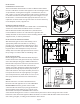
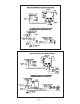
INTERNAL WIRING CONNECTIONS FOR THE CAS UNIT
Refer to Figure 3 for the internal wiring of the CAS-6/7 unit.
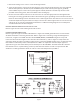
EXTERNAL WIRING CONNECTIONS
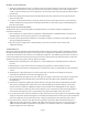
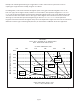
Refer to Figure 4 for typical 120 VAC oil red burner or Figure 5 for 24 VAC gas red burner connections that
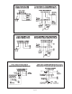
should be used when connecting the CAS unit. Refer to Figure 6 for connecting a single 120 VAC appliance
to the CAS, or Figure 7 for 24 VAC. The three wires BURNER, WHITE, and ORANGE in Figure 4 correspond
to the same wires shown in Figures 6 & 10. The three wires labeled 1, 2, and 3 in Figure 5 correspond to the
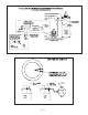
same wires shown in Figures 7-9. Refer to Figures 8-10 for connecting multiple appliances to one CAS unit. Note
that an RJR-5 or RJR-6 relay and/or a CAC-24, CAC-120 or DIP-1 are required on certain multiple-appliance
applications. Figure 11 shows how the pressure switch port on the CAC/DIP-1 should be attached to the CAS.
Note that the correct
1
⁄4" plastic tubing on the top of the CAS unit must be cut and a 3-way male barb TEE
suitable for
1
⁄4" tubing installed as shown in order to connect the CAC pressure port/DIP-1.
1. Remove the wiring access cover to access the wiring terminals.
2. Select the appropriate control relay for the appliance control system voltage from the two relays supplied
with the CAS system (see illustration). Use the 24VAC relay for a 24V control system (typical gas- red),
or the 120VAC relay for a 120V control system (typical oil- red). Install the selected relay into the socket
provided on the wiring panel, and secure with the wire retaining clip.
3. Use the enclosed conduit connectors or like connectors to route the appropriate wires through the CAS
housing. The incoming ground wire must be attached to the green grounding screw located near the wire
terminals. The following sections describe the most common applications. The references to various series of
control kits implies that any kit in that series may be used. Such as when a gure refers to a CK-60 series kit,
a CK-60, 61, 62, etc. may be used. If further information or additional wiring diagrams are needed please
consult Field Controls' technical support.
Figure 4
Figure 5