
Install Instructions
page 2
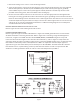
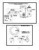
SIZING AND SETUP
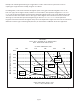
Diagram A shows the maximum equivalent length and size of duct pipe that should be used when installing
the CAS-6 system; Diagram B shows the same for the CAS-7. Using this table will help ensure that the proper
amount of air is drawn into the structure as needed by the appliance. The de ned regions shown correspond
to the CAS's air ow characteristics when using various sizes of duct pipe for the CAS-6 and CAS-7. Follow the
guidelines below to properly size and set up the CAS system.
1. Determine the input ring rate of the appliance, or the total ring rate of multiple appliances that will
be used.
2. Determine the location of the CAS unit according to the guidelines in the Installation section.
3. Determine where the intake air StarKap will be located based on the recommendations in the Installation
section.
4. On Diagram A or B (as appropriate), locate the point that corresponds to the ring rate along the
horizontal axis and draw a vertical line through this point.
5. The line should pass through at least one of the pipe size regions on the table. The regions correspond to
the maximum equivalent lengths of the given diameter duct pipe that will be adequately sized for
the application.
6. Calculate the equivalent length of the smaller diameter duct pipe that may be used with the particular
CAS system, including elbows, reducer/increaser and other ttings (except the StarKap, see the Field
Controls Contractor Reference Guide). The e ects of the StarKap are already gured into the diagram,
so do not attempt to include any value for the StarKap in your calculation for equivalent length. Draw a
horizontal line through the point corresponding to the equivalent length on the vertical axis.
7. Locate the intersection of the two drawn lines. If the intersection lies in the region for the equivalent length
of pipe for which the equivalent length was calculated, then that diameter of duct pipe will be of su cient
size for the application. If not, then repeat step 7 using a larger diameter duct, then proceed to step 9.
8. If the intersection of the two lines falls into the larger duct region, then that diameter duct will be of
su cient size for the application. If it falls to the right of the larger pipe region, then even larger pipe or
additional CAS units will be required for the application. For assistance in this case, call Field Controls
Technical Support at 1-800-742-8368.
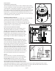
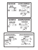
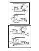
GENERAL SYSTEM OPERATION
1. The thermostat (wall thermostat, or aquastat) calls for heat and energizes a relay which activates the CAS
unit. After the CAS fan has come up to speed, an internal air pressure switch closes and completes the
circuit to allow the burner to re. If the appliance is power vented, the venter will typically activate before
the CAS unit.
2. After the heating requirement has been satis ed, the thermostat circuit will open and deactivate the
burner and CAS unit.
3. For power vented systems with a post purge device, the power venter will operate for a period of time
determined by the post purge timer setting after the burner has shut o to purge remaining ue gases
from the vent system.
INSTALLATION SAFETY INSTRUCTIONS
CAUTION: This device must be installed by a quali ed installer in accordance with the manufacturer’s
installation instructions.
1. This combustion air system must be installed by a quali ed installer. “Quali ed Installer” shall mean an
individual who has been properly trained or a licensed installer.
2. Plan the system layout before installation to avoid the possibility of accidental contact with concealed
wiring or plumbing inside walls.
3. Disconnect power supply before making wiring connections to prevent electrical shock and
equipment damage.