
Install Instructions

page 11
MAINTENANCE
1. Inspect the system annually to ensure proper operation by observing that the fan activates when a call for
heat occurs and deactivates when the call for heat is satis ed.
2. Disconnect power to the CAS unit and repeat Step 1. NOTE: The unit should not run and the appliance
should not re in this condition.
3. Inspect the duct pipe for loose joints, damage, and security to the CAS unit and StarKap.
4. Clear any obstructions, if present, from the inlet of the StarKap and the outlet of the CAS unit.
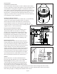
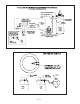
5. Periodically, the fan blade chamber may need cleaning. First, disconnect the power supply to the CAS.
Next, disconnect the duct pipe from the unit. Then remove the top pan and clean the fan housing area as
needed. Reattach the top pan, reconnect the duct pipe and the power supply.
CAUTION: A minimum clearance of 1" must be maintained between the bottom of the fan blade and the
top of the metal surface underneath. FAILURE TO MAINTAIN THIS CLEARANCE MAY RESULT IN A FIRE
HAZARD AND WILL VOID THE WARRANTY.
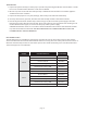
REPLACEMENT PARTS
The following items are available for replacement, if needed. In order to replace these parts, power must be
disconnected and the unit must be disassembled. If this is necessary, take note of the positions and locations of
whatever items that may need to be removed to replace other items. If in doubt, please consult Field Controls
Technical Support at 1-800-742-8368.
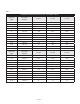
MODEL ITEM DESCRIPTION PART NUMBER
CAS-6
AC Motor 46363400
Blower Wheel 46363600
Pressure Switch 46363500
Timer Relay 46144700
24 VAC Control Relay SPDT 46080200
120 VAC Contro l R el ay SPDT 4 611110 0
CAS-7
AC Motor 46363400
Blower Wheel 46363700
Pressure Switch 46363500
Timer Relay 46144700
24 VAC Control Relay SPDT 46080200
120 VAC Contro l R el ay SPDT 4 611110 0