
Cascade Series Install Manual


page 9 of 16
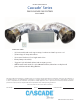
INSTALLATION: FAN & DUCT
NOTES:
• The fan assembly must be soundly supported by attachment to structurally sound framing. Provide
additional framing with minimum 2-by-4 lumber as needed for fan support.
• Each fan assembly should be positioned with at least 24” of free space in front of the fan, for air to be freely
blown into the attic by the fan.
• Position the fan with a slight upward angle and in a direction minimizing disturbance to attic insulation.
• The acoustical duct should be installed with a gentle bend of close to 90 degrees, from vertical to nearly
horizontal, to minimize fan sound inside the living space. It must not be kinked or bent sharply, especially
where leading into the fan.
• The acoustical duct must be installed with the air ow direction arrow (as marked on the duct) pointing
downstream (towards the fan).
1. Lay the fan assembly on top of the ceiling joists,
within a few feet of the damper assembly and
and underneath the area where the fan will be
suspended in place.
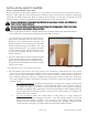
2. Rotate and brace the fan assembly so that the
electrical handy-box on the fan is in the 12-o’clock
position (on the top of the fan). This is important to
avoid twisting the duct, while having the fan’s
electrical handy-box within the 10- to 2-o’clock
position once installed.
3. Adjust the exible duct collar on the upstream end
of the duct to be as loose as possible. Squeeze
and position the exible acoustic duct collar over
the oval-shaped collar on the damper box, and attach
using 3 of the screws provided, or other suitable
screws. Note that twisting the duct will cause the
fan to try to roll out of position. Seal the joint with
approved duct tape, mastic, or other approved means.
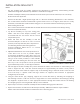
4. Lift and support the fan assembly into position beneath the rafters, truss structure or other framing to be
used to support the fan, with the electrical handy box at approximately the twelve-o-clock position.
Attach both ends of the metal fan support strap to the framing using a minimum of two screws for each
end of the strap. 1” drywall screws and large washers are supplied; other fasteners of appropriate
strength may also be used.
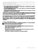
5. Using the black woven poly strapping, support the acoustic ex duct by attaching the strapping to
attic fram
ing as shown. Fold each end over a large washer 2-3 times and fasten to the framing by driving
the supplied 1” drywall screws or other appropriate fasteners through the washer and into the framing.
The strapping may be cut to length with ordinary scissors if desired.
6. Repeat steps 1-5 for the second fan assembly. The fans should be facing opposite directions.
7. Replace the insulation around and over the damper assembly. Additional insulation may be added to
further reduce heat transfer and fan noised from the attic to the living space.
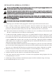
FIGURE 3: FAN & DUCT STRAPS DETAIL
P/N 780105002 01/21 Rev A