
Installation Guide

page 2
COLLAR INSTALLATION
WHEN SHIPPED WITH A COLLAR
To attach the collar to the flue, see Figure 2
and follow these instructions:
Bend the two ears at the front corners 1.
of the collar outward. Bend 90°, ¼”
behind the single hole on the straps.
Insert clamping screw in ears on collar 2.
and bolt the remainder of the
collar together.
Hold the collar against the side of the 3.
flue in the exact position it is to be
installed (shown by dotted lines) and
mark the outline of the collar on
the flue.
Cut a hole in the flue about ½” inside 4.
of the outline.
Make a series of cuts about ½” apart 5.
from the edge of this hole to the
outline marks.
Strap the collar to the flue pipe. 6.
Bend the tabs formed by the series of cuts outward against the inside of the collar to make a tight joint. 7.
Insert the draft control. (See Installation & Adjustment) 8.
If flue pipe is made of material too heavy to bend out into collar, make the diameter of the opening within
½" of the inside diameter of the collar. Seal with high temperature RTV silicone or high temperature foil tape
UL listed for the temperature of the application. For proper settings and operation of the burner and the draft,
combustion testing instrumentation and draft gauges must be used.
Figure 1
1/2” Approx
Figure 2
BAROMETRIC DRAFT CONTROLS WITH OR WITHOUT COLLAR
The Field RC is furnished as standard equipment on many leading brands of oil fired heating equipment. It is
calibrated to allow for easy adjustment to the furnace or boiler manufacturer’s specifications. Designed for
draft settings from .02” to 08” of W.C.
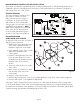
CONTROL LOCATIONS
The control should be located as close
as possible to a furnace or boiler
and positioned as shown in Figure 1.
It should be 18” from a stack switch
and at least 18” from a combustible
ceiling or wall. Do not locate in a room
separated from the appliance. NOTE:
When a sheet metal tee is used instead
of the collar, the “B” dimension must
not be less than indicated for proper
operation. (See Figure 2 and Table 1)