
Install Instructions


WARNING: Never expose eyes or skin to UVC light from any source. Looking directly at the UVC light may cause permanent eye damage
or blindness.Never operate the Duo-2000 Air Purifying System out of the plenum. Avoid touching the glass portion of the lamp with your hands.
Page 4 of 12
DUO-2000 INSTALLATION INSTRUCTIONS
DUO-2000 INSTALLATION INSTRUCTIONS
INSTALLATION INSTRUCTIONS FOR DUO-2000 LAMP
NSTALLATION INSTRUCTIONS FOR DUO-2000 LAMP
NOTE: : Due to directional airfl ow installation options, the Healthy Home System 3x3 Product Brand Label is
NOTE: : Due to directional airfl ow installation options, the Healthy Home System 3x3 Product Brand Label is
enclosed for proper upright placement at the fi eld installation. The Duo-2000 installation is specifi c
enclosed for proper upright placement at the fi eld installation. The Duo-2000 installation is specifi c
to direction of airfl ow and must be properly positioned when choosing upfl ow, downfl ow, or hori
to direction of airfl ow and must be properly positioned when choosing upfl ow, downfl ow, or hori
zontal airfl ow application. Pay attention to directional airfl ow arrow for proper installation. The
zontal airfl ow application. Pay attention to directional airfl ow arrow for proper installation. The
installation of the Duo-2000 may be on the return air side, supply air side, or above the AC-Coil in the
installation of the Duo-2000 may be on the return air side, supply air side, or above the AC-Coil in the
supply plenum of the HVAC system. For best results, the HVAC air fi lter should be upgraded to a
supply plenum of the HVAC system. For best results, the HVAC air fi lter should be upgraded to a
Field Controls High Effi ciency FC8 or FC11 pleated media air cleaner. Do not locate the Duo-2000
Field Controls High Effi ciency FC8 or FC11 pleated media air cleaner. Do not locate the Duo-2000
within 24 inches (direct exposure) of plastic materials or air fi lters. UVC radiation will degrade many
within 24 inches (direct exposure) of plastic materials or air fi lters. UVC radiation will degrade many
plastic materials over time with direct exposure. The Duo-2000 is designed to be installed on indoor
plastic materials over time with direct exposure. The Duo-2000 is designed to be installed on indoor
HVAC forced air ducted systems. Do Not install outdoors. Product is not designed to be exposed to
HVAC forced air ducted systems. Do Not install outdoors. Product is not designed to be exposed to
outdoor elements.
outdoor elements.
WARNING: Disconnect power to all equipment before beginning this installation! Refer to all warning
WARNING: Disconnect power to all equipment before beginning this installation! Refer to all warning
and
and
cautionary statements as given in the included main installation instructions!
cautionary statements as given in the included main installation instructions!
WARNING: Make sure unit is unplugged before installing the lamp
WARNING: Make sure unit is unplugged before installing the lamp
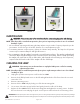
1. The ballast is factory set to 120 VAC. The voltage can be changed in the fi eld to 230 VAC by sliding
1. The ballast is factory set to 120 VAC. The voltage can be changed in the fi eld to 230 VAC by sliding
the
the
voltage selector switch in (Figure 1) to the 230 volt position. The plug must be replaced and
voltage selector switch in (Figure 1) to the 230 volt position. The plug must be replaced and
wiring
wiring
must
must
be done to applicable electrical codes.
be done to applicable electrical codes.
2. Remove the front electrical cover from the Duo-2000.
2. Remove the front electrical cover from the Duo-2000.
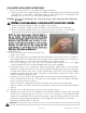
3. Do not touch the bulb lamp glass section with bare hands. Wear oil-free cotton type gloves when handling
3. Do not touch the bulb lamp glass section with bare hands. Wear oil-free cotton type gloves when handling
ger
ger
micidal glass bulb.
micidal glass bulb.
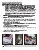
4. Remove Lamp (LT015) from packaging and slide non-pinned end through grommet.
4. Remove Lamp (LT015) from packaging and slide non-pinned end through grommet.
5. Loosen lamp
5. Loosen lamp
clip
clip
and insert lamp so that the end of the lamp is inside the unit.
and insert lamp so that the end of the lamp is inside the unit.
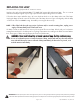
6. Tighten lamp clip using the brass knurl. Make sure the lamp clip tightens around the plastic part of the lamp
6. Tighten lamp clip using the brass knurl. Make sure the lamp clip tightens around the plastic part of the lamp
and not the glass. See Figure 2.
and not the glass. See Figure 2.
7. Connect ballast to the four pins on the lamp using the connector. See Figure 3.
7. Connect ballast to the four pins on the lamp using the connector. See Figure 3.
8. Wipe down the lamp with the supplied alcohol wipe.
8. Wipe down the lamp with the supplied alcohol wipe.
P/N 46638600 09/18 Rev E
FIGURE 1
FIGURE 2 FIGURE 3