
Overview of Primary Product
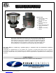
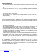
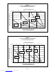
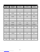
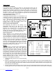
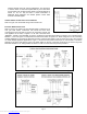
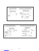
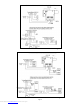
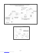
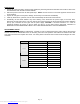

Figure 1
INSTALLATION
P
LACEMENT OF THE CAS UNIT
The motorized CAS unit should be located on a flat horizontal surface near the
combustion air intake of the appliance. Two mounting brackets are provided for
securing the unit against a solid structure, such as a wall, column, or the side of the
appliance itself. Use the included screws to attach the brackets to the CAS housing
as shown in Figure 1. Secure the brackets to a solid structure with appropriate
fasteners. It is not required to use the brackets as long as the unit is located so that it
may not be bumped, moved, or tipped over.
I
NTAKE AIR STARKAP LOCATION
The StarKap should be located on an outside wall or roof
maintaining clearances to other intake and exhaust vents
in accordance with the National Fuel Gas Code, ANSI
Z223.1, manufacturer's recommendations and/ors local
codes which are applicable. The StarKap should be
located at least 10 feet from a building exhaust outlet,
equipment vent, or chimney termination.
Figure 2
I
NSTALLATION OF INTAKE AIR STARKAP
After determining the location of the StarKap, cut an
appropriately sized hole in the wall or roof, taking
precautions to avoid interference with wiring or other
plumbing in the structure to be cut. Pre-attach a short
length of duct to the StarKap if necessary. Insert the
StarKap and secure with appropriate fasteners. Flash in
the opening in accordance with local building codes.
I
NSTALLATION OF DUCT
Refer to Diagram A or B to determine what size pipe is
needed. Connect the duct pipe from the top of the CAS
unit to the StarKap. If using pipe of different diameter than
the CAS component connections, attach increaser/reducer
fittings as close to the CAS unit and to the StarKap as
possible. The duct should be supported with appropriate
mounting straps from floor joists, walls, or other solid
structures. The straps should be placed so as to keep the
duct work out of passageways (See Figure 2). For best
performance, install elbows or tees no closer than 3 pipe
diameters from the inlet of the CAS unit.
Figure 3
WIRING
Wire the CAS unit in accordance with the National Electric
Code and applicable local codes. UNIT MUST BE
GROUNDED. Check the ground circuit to make certain
that the unit has been properly grounded. The wiring
should be protected by an over-current circuit device rated
at 20 amperes. CAUTION must be taken to ensure that
the wiring does not come in contact with any heat source.
All line voltage and control circuits between the CAS unit
and the appliance MUST be wired in accordance with the
National Electrical Code for Class I wiring or higher,
according to the installation environment.
1. Remove the wiring access cover to access the wiring
terminals.
2. Select the appropriate control relay for the appliance control system voltage from the two relays supplied with the
CAS system (see illustration) Use the 24VAC relay for a 24V control system (typical gas-fired), or the 120VAC relay
for a 120V control system (typical oil-fired). Install the selected relay into the socket provided on the wiring panel, and
secure with the wire retaining clip.
3. Use the enclosed conduit connectors or like connectors to route the appropriate wires through the CAS housing. The
incoming ground wire must be attached to the green grounding screw located near the wire terminals. The following
Page 5
Downloaded from www.Manualslib.com manuals search engine