
User Guide


page 7
WARNING: Disconnect power supply before installation to prevent personal injury or death from
electrical shock and equipment damage. Wire the power venter motor and controls in accordance with
the National Electrical Code and applicable local codes.
CAUTION: Unit must be grounded. Check ground circuit to make certain that the unit has been
properly grounded.
CAUTION: All parts of this product that are capable of conducting electrical current are grounded. If
grounding wires, screws, straps, clips, nuts, or washers used to complete a path to ground are removed for
service, they must be returned to their original position and properly fastened. The wiring should be protected
by an over-current circuit device rated at 15 amperes.
CAUTION: Power venter wiring must not come in contact with any heat source. All line voltage and safety
control circuits between the power venter and the appliance MUST be wired in accordance with the National
Electrical Code for Class 1 wiring or equivalent.
Diagram C
SYSTEM CONTROL CHECK OUT PROCEDURES
1. Adjust the thermostat to call for heat and observe the power venting system for
proper operation sequence. (Repeat if necessary.)
a. Thermostat calls for heat.
b. Relay in Control Kit is energized and Power Venter motor starts.
c. Air pressure switch closes and ignition sequence starts.
d. Thermostat is satised, the appliance burner stops.
e. Power Venter continues to run.
f. Power Venter stops after the post purge cycle.
2. After verifying the correct operation of the system as stated above, repeat the
procedure. While the appliance is operating, disconnect power to the Power
Venter motor. As the venter motor slows, the air pressure switch contacts will
open and stop the appliance burner operation. This simulates a venter failure
and tests the fan proving switch and wiring.
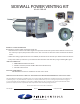
AIR FLOW ADJUSTMENTS
In order to obtain proper system draft, the power venter has an airow adjustment damper built-in. (See
Figure 12) This damper should be used to make coarse draft adjustments while the barometric should be used
for ner adjustments. Changes in the adjustment of the 4" MG-1 Draft Control should be made by adding
WIRING
Refer to Diagram C for guidance in wiring the Power Venter and Control Kit to the appliance.
Figure 12