
User Guide


page 6
Figure 7
Figure 10
Figure 9
Figure 8
Figure 11
ITEMS INCLUDED IN CK-43F CONTROL KIT:
1- Junction box with mounted air pressure switch and post
purge relay/timer
1- 2' Length of
1
⁄4" aluminum tubing
1-
1
⁄4" tubing connector
1- Flexible conduit connector
1- 4" MG-1 Barometric Draft Control
DRAFT CONTROL INSTALLATION
1. Install a vent pipe reducer or increaser, if needed, into the tee and
fasten using sheet metal screws. (See Figure 7)
2. If using a Type B Vent Tee, the opening of the Tee, at the draft control
mounting location, should be sealed with a high temperature sealant or
equivalent.
3. Insert the draft control into the tee. The front face of the control MUST
be plumb and the bearing surfaces MUST be level whether the control
is on a horizontal, vertical or sloping ue pipe. Use a spirit level and
level accurately. Secure the control in tee by using sheet metal screws.
NOTE: Do not install the draft control in a vent pipe tee in the conguration as
shown in Figure 8.
MOUNTING JUNCTION BOX
The junction box can be mounted near the venter or remotely mounted up to
100' away from the venter. (See Figures 9 & 10)
1. Remove one of the knockouts from the side of the junction box where the
pressure switch is mounted. Install the exible conduit connector onto the
CK-43F junction box and secure with fastening nut. If remote mounting
the CK-43F junction box, mount the exible conduit connector onto a 2"
x 4" installer supplied junction box. (See Figure 10)
2. Fasten the exible conduit from the SWG Venter into the conduit
connector. Mount the CK-43F junction box or installer supplied
junction box onto the wall or oor joist without straining the exible
conduit. Fasten the CK-43F junction box to the wall through the four
dimpled locations on the base of the box. NOTE: The Control Kit
box must be mounted so that the air pressure switch is vertical. If not
mounted vertically, the control system will not operate properly.
PRESSURE SWITCH SENSING TUBE INSTALLATION
1. Attach the
1
⁄4" tubing connector to the pressure tube on the SWG
Venter. (See Figure 11)
2. Connect the supplied
1
⁄4" aluminum tubing to the tubing connector.
Route the tubing to the CK-43F junction box and connect the tubing
to the pressure switch. When routing the tubing, avoid kinking the
tubing by bending the tubing too sharply.
For remote mounted CK-43F Junction Box, use a
1
⁄4" OD copper,
aluminum or plastic tubing and route the tubing to avoid contact with
any heat source.
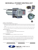
INSTALLATION INSTRUCTIONS FOR CK-43F CONTROL KIT
Designed for use with the SWG Series Power Venter for controlling
Natural Gas and LP Gas Draft Induced appliances.