
User Guide


page 4
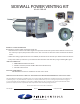
Diagram B
f. The vent termination should not be mounted directly above, or within 3' horizontally from an oil tank
vent or gas meter.
g. The bottom of the vent terminal shall be located at least 12" above nished grade or maximum
expected snow height.
3. After determining the location of the venting system termination point (See Diagram A), cut a square hole
through the wall 1" larger than the outer pipe diameter of the power venter. (See Figure 1)
4. Seal the back side of the base plate around the outer pipe of the venter and the conduit with a bead
of high temperature silicone sealant. (See Figure 3) Mount the power venter through the wall, keeping
the outer pipe centered in the hole. (See Figure 1) Fasten the power venter to the outside wall with
appropriate fasteners. Seal the edges of the power venter base plate to the wall with a high temperature
silicone sealant.
NOTE: If mounting the power venter through a combustible wall material and the ue gas temperature is
above 400°F at the power venter inlet, line the square hole with a piece of corrosion resistant sheet metal or
non-combustible material. The liner piece should be the same width as the wall section. (See Figure 1) The
power venter has a maximum ue gas temperature of 550°F at the venter inlet. For installation through walls
over 8" thick, use an SWG Series Extension Kit, Model PEK-4HD.
5. Remove the end pipe cover screws on the sides of the outside pipe and remove end pipe cover. Then
mount the backing plate over the outer pipe and route the exible conduit and pressure switch tube
through the holes provided in the backing plate. Fasten the backing plate to the inside wall with
appropriate fasteners. (See Figure 3) Re-install cover and end pipe screws.
CONNECTING POWER VENTER TO APPLIANCE
The venting system should be installed and supported in accordance with the National Fuel Gas Code,
ANSI Z223.1, CGA Standards B149.1-M91, B149.2-M91, or in accordance with any local codes. A vent pipe
connector shall be supported for the design and weight of the material employed, to maintain clearances,
prevent physical damage and separation of joints.
If mounting venting system near combustible materials, refer to Diagram B for allowable installation
clearances. Always check local code requirements for code restrictions.
Route the vent pipe from the appliance to the power venter using the least number of elbows possible. The
horizontal section of the vent pipe should have a slight upward slope from the appliance to the power venter.
For clearances to combustible materials, multiple appliance venting, and other installation requirements,
refer to the National Fuel Gas Code ANSI Z223.1, CGA Standards B149.1-M91, B149.2-M91, and/or any
applicable local codes or appliance manufacturer’s installation instructions.