
User Guide


page 3
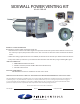
INSTALLATION OF THE SWG POWER VENTER
1. Remove power venter from box and inspect unit for damage.
If the carton has been crushed or mutilated, check unit very
carefully for damage. Rotate blower wheel to insure that the
motor and blower wheel rotate freely. DO NOT install if any
damage is apparent.
2. Location of the termination of the venting system should be
installed in accordance with the National Fuel Gas Code,
ANSI Z223.1, CGA Standards B149.1-M91, B149.2-M91,
manufacturer's recommendations, and/or local codes which
are applicable. See requirements below or refer to installation
location Diagram A for typical locations.
a. The exit termination of mechanical draft systems shall not be
less than 7' above grade when located adjacent to
public walkways.
b. A venting system shall terminate at least 3' above any forced air inlet
located within 10'. For Canadian applications, a venting system shall
terminate more than 6' away from a mechanical air
supply inlet.
c. The venting system of other than a direct vent appliance shall
terminate at least 4' below, 4' horizontally from, or 1' above any
door, window or gravity air inlet into the building. For Canadian
applications, according to CAN/CGA Standards B149.1-M91 and
B149.2-M91, 12" clearance is required for inputs up to and including
100,000 BTU/HR and 3' for inputs exceeding 100,000
BTU/HR.
d. The vent termination of a direct vent appliance with an
input of 50,000 BTUs per hour or less, shall be located
at least 9" from any opening through which vented
gases could enter the building. With an input over
50,000 BTUs per hour, a 12" termination clearance
shall be required.
e. The vent termination point shall not be installed closer
than 3' from an inside corner of an L-shaped structure.
Figure 1
Diagram A
Figure 2
Figure 3