
User Guide


page 2
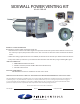
INSTALLATION OF SWG POWER VENTER
WARNING: Failure to install, maintain and/or operate the power venting system in accordance with
the manufacturer’s instructions may result in re, personal injury, or death.
WARNING: Bodily injury can result from high voltage electrical components, fast moving fans, and
combustible gas. For protection from these inherent hazards during installation and servicing, the
electrical supply must be disconnected and the main gas valve must be turned o. If operating checks
must be performed with the unit operating, it is the technician’s responsibility to recognize these hazards
and proceed safely.
INSTALLATION SAFETY INSTRUCTIONS
1. Safety inspection of a venting system should be performed before and after installing a power
venting system on an existing or new appliance. Procedures to follow are those recommended by the
National Fuel Gas Code, ANSI Z223.1, CGA Standard B149.1-M91 or B149.2-M91, or refer to the
General Installation Inspection section of this manual.
2. Plan the vent system layout before installation to avoid the possibility of accidental contact with
concealed wiring or plumbing inside walls.
3. Single wall vent pipe (refer to Diagram B) may be used to join the appliance to the power venter.
If proper clearances cannot be maintained from combustible material, Type B vent pipe should be
used. Refer to national or local codes for guidelines.
4. Disconnect power supply before making wiring connections to prevent electrical shock and
equipment damage.
5. This equipment is designed to overcome minor negative pressure conditions. To ensure extreme
negative pressure does not exist, follow the General Installation Inspection section of this manual.
6. Air ow adjustment MUST be made to ensure appliance eciency. This should be done at the
appliance exhaust outlet with a velocity meter or draft gauge.
7. On gas-red furnaces, a barometric draft control must be installed to regulate proper air ow and
uctuations in the system’s air ow during operation. Fluctuations may come from wind loads on the
outlet of the power venter or house depressurization during windy days.
8. The air pressure switch must be adjusted to assure safe operation. Failure to adjust the air pressure
switch as specied later in these instructions, could lead to improper operation of the venting system
and furnace which will result in product damage, personal injury, or death.
PROCEDURE FOR CALCULATING TOTAL EQUIVALENT PIPE LENGTH IN FEET
1. Calculate the total equivalent feet for each type of tting used in the venting system from Table 1 below.
2. Calculate the total amount of feet for the straight lengths of vent pipe.
3. Add the equivalent feet for the ttings with the total amount of feet of straight lengths. This will
approximate the total equivalent feet of the vent system. The total equivalent feet must be less than the
maximum equivalent vent length as shown in OEM instructions.
EQUIVALENT LENGTH (FEET) OF VENT PIPE FOR
VENT PIPE FITTINGS
Vent Pipe Fittings 4" Vent Pipe Diameter
90º ELBOW 7
45º ELBOW 4
Example: System Pipe Size = 4"
Step 1 Two 4" 90º Elbows @ 7 feet each = 14 Ft.
Step 2 Ten 2 Foot Lengths of 4" Pipe = 20 Ft.
Step 3 Total Equivalent Feet = 14 Ft. + 20 Ft. = 34 Ft.
Table 1