
User Guide


page 9
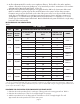
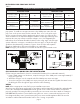
PART NUMBERS
MODEL REPAIR MOTOR ASSEMBLY BLOWER WHEEL
SWG–3 46196601 46131800
SWG/SWGII–4HD, SWG–4s 46234800 46310400
SWG/SWGII–5, SWG–5s 46234900 46213800
SWG/SWGII–6, SWG–6s 46235000 46385800
SWG–7 46152401 46154700
SWG–8 46460101 46154800
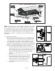
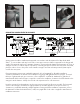
SWG Repair
Motor Assembly
SWGII Repair
Motor Assembly
Blower
Wheel
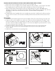
MAINTENANCE
Motor:1. Inspect the motor once a year - motor should rotate freely. To prolong the life of the motor, it must
be lubricated with six drops of SWG Superlube, Part # 46226200, annually.
Wheel:2. Inspect the power venter wheel annually to clear any soot, ash or coating which inhibits either
rotation or air flow. Remove all foreign materials before operating.
Vent System:3. Inspect all vent connections annually for looseness, for evidence of corrosion and for flue
gas leakage. Replace, seal or tighten pipe connections if necessary. Check the power venter choke plate
to ensure it is secured in place. Check the barometric draft control, if installed, to ensure the gate
swings freely.
System Safety Devices:4. With the heating system operating, disconnect the pressure sensing tube from
the pressure switch on the CK Kit. This will stop the burner operation. Re-connecting the tube will relight
the burner. For 30 millivolt operating systems, disconnect one lead of the spill switch circuit from the
thermocouple junction block. This will shut off the pilot and the burner. Re-connection will allow relighting
the pilot.
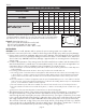
REPLACEMENT PARTS
Should the motor or blower wheel need replacing, the following replacement items are available. The Repair
Motor Assembly contains the Motor and Blower Wheel factory assembled to a mounting bracket.
Table 4
Visually determine that the main burner is burning properly; i.e., no floating, lifting or flashbacks. When 5.
performing smoke test on oil-fired systems, the burner should operate at a zero to a trace smoke. This can
indicate reduced available combustion air to burner.
If appliances are equipped with high and low flame control or flame modulation, check for proper main 6.
burner operation at low flame.
Test for spillage at draft hood or barometric draft control opening and burner inlet air location after 5 7.
minutes of main burner operation. Use a draft gauge, flame of a match or candle, smoke from a cigarette,
cigar or pipe. If spillage occurs, adequate air is not available. Shut off heating appliance thermostat and
check for spillage around the draft hood, barometric draft control or burner inlet air location after power
venter has stopped operation. If a flow reversal is noticed, house de-pressurization is occurring and make up
air is required. For oil-fired systems, this may be noticed by oil fume smell after post purge cycle.
Turn on all fuel burning appliances within the same room so that they will operate at their maximum input. 8.
Then repeat Steps 5 through 7.
Return doors, windows, exhaust fans, fireplace dampers and any other fuel-burning appliances to their 9.
previous condition of use.