
User Guide


page 5
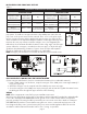
Diagram A
Figure 4
Figure 2
Figure 3
NOTE: If mounting the power venter though a combustible wall material
and the flue gas temperature is above 400ºF at the power venter inlet,
line the square hole with a piece of corrosion resistant sheet metal or
non-combustible material. The liner piece should be the same width as
the wall section. (See Figure 3) The power venter has a maximum flue
gas temperature of 550ºF at the venter inlet. For installation in wall
thicknesses over 8 inches, use SWG Series Through Wall Extension Kit,
Model PEK.
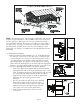
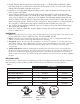
Backing Plate Installation4.
One Piece Backing Plate Installation (3", 6", 8" Models) Remove a.
the end pipe cover screws on the sides of the outside pipe and
remove end pipe cover. Then mount the backing plate over the
outer pipe and route the flexible conduit and pressure switch
tube (if applicable) through the holes provided in the backing
plate. Fasten the backing plate to the inside wall with appropriate
fasteners. (See Figure 4) Re-install the end pipe cover and screws.
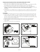
Two Piece Backing Plate Installation (4" and 5" Models):b.
i. Position the Upper Backing Plate Half on the inside wall by
placing the plate half on the inside wall and up to the venter
body, locating the air pressure sensing tube through the small
slot in the plate half and the flexible conduit through the
larger slot, as shown in Figure 5. Install an appropriate
fastener in the upper right corner hole in the
plate half.
ii. Cut off or bend the two tabs of the Lower Backing
Plate Half inward (See Figure 6) and position it
on the inside wall as shown in Figure 7 and install
appropriate fasteners through the upper left and
lower right corner holes in both plate halves.
iii. Install an appropriate fastener in the lower left
corner hole.