
Hardware Guide

Reproduction forbidden without Fibocom Wireless Inc. written authorization - All rights reserved.
FIBOCOM MC610 Series Hardware Guide 47/71
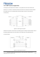
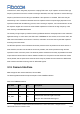
3.10.2 HP Headphone Jack
Table 3-17 HP pins
HP_R
O
33
Earphone right channel signal
HP_L
O
34
Earphone left channel signal
Module earphone output power: 25 mW @ ± 1.8 V on 32 Ohm load, gain range: -18 dB to + 0 dB with 3
dB steps (4-bit programmable gain).
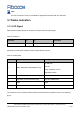
3.10.3 MIC Interface
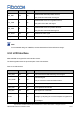
Table 3-18 MIC pins
HEADMIC_P
I
99
Earphone MIC input positive
HEADMIC_N
I
100
Earphone MIC input negative
HEADMIC_BIAS
PO
81
Bias voltage of earphone MIC
MIC_P
I
29
MIC input positive
MIC_N
I
28
MIC input negative
MIC_BIAS
PO
30
MIC bias voltage
8 levels of gain amplification within MIC input are adjustable, range: 0 dB to +36 dB (3-bit programmable
gain, 0/3/6/12/18/24/30/36 dB).
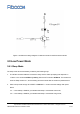
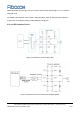
3.10.3.1 MIC Interface Circuit
The MIC_P/MIC_N channel has no internal bias voltage and must be used with an external bias circuit.
Please refer to the picture below: