
Hardware Guide


Reproduction forbidden without Fibocom Wireless Inc. written authorization - All rights reserved.
FIBOCOM MC610 Series Hardware Guide 38/71
C6
USIM_VDD
R2
USIM_RESET
USIM_PRESENCE
USIM_CLK
USIM_DATA
R4
R3
R7
C5 C4 C3 C1C2
RV5
RV1
RV2
RV3
RV4
MODULE
VIO_1V8
R6
R5
SIM_CONNECTOR
SIM016-8P-220P
Set to high level detection SIM card
VCC
GND
RST
DET
CLK
DATA
GND
GND
POL
VPP
1
2
3
8
5
6
10
9
7
4
22R
22R
22R
47K
4.7K
SIM
NC
0.1uF
33pF
33pF
33pF
33pF
33pF
RV1-RV5 Recommend EGA10402V05A2
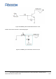
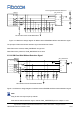
Figure 3-12 Reference design diagram for MC610 series USIM/SIM interface with detection signal
The principle of SIM card slot with detection signal is described as follows:
When SIM card is inserted, USIM_PRESENCE is high level.
When SIM card is pulled out, USIM_PRESENCE is low level.
3.5.2.2 SIM Card Slot Without Detection Signal
C6
USIM_VDD
R2
USIM_RESET
USIM_PRESENCE
USIM_CLK
USIM_DATA
R4
R3
R7
C5 C4 C1C2
RV5
RV1
RV3
RV4
MODULE
SIM_CONNECTOR
VCC
GND
RST
CLK
DATA
GND
GND
VPP
1
2
3
5
6
8
7
4
22R
22R
22R
10K
SIM
0.1uF
33pF
33pF
33pF
33pF
RV1-RV5 Recommend EGA10402V05A2
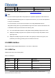
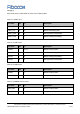
Figure 3-13 Reference design diagram for MC610 series USIM/SIM interfaces without detection signal
SIM_IO does not require a pull-up resistor.
SIM card slot without detection signal, module USIM_ PRESENCE pins are subject to 10 kV
Note: