
Hardware Guide

Reproduction forbidden without Fibocom Wireless Inc. written authorization - All rights reserved.
FIBOCOM MC610 Series Hardware Guide 30/71
The above results are laboratory test data, with a deviation of ±10%.
3.3 Control Signal
MC610 series modules provide 2-channel control signals to start up/shut down and reset the module.
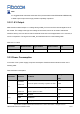
The pin definition is defined as shown in the following table:
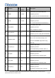
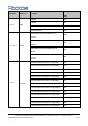
Table 3-6 Control signal
Pin Name
I/O
Pin
Description
EMERG_R
ST/
RESET_N
I
37, 123
When the module is working, provide RESET with a Tst (100 ms) low
level, and then rise, reset the module.
PWRKEY
I
14
The minimum duration of low level is 2s when it is started up at a low
level, and 3.1s when it is shut down at a low level.
3.3.1 Module Startup
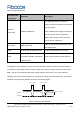
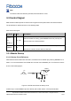
3.3.1.1 Startup Circuit Reference
When MC610 series modules are shut down, the module can be started up by lowering PWRKEY for at
least 2 s. It is recommended to use OC/OD drive circuit to control PWRKEY pins. The reference circuit is
shown in the following figure:
4.7K
47K
10nF
PWRKEY
Turn on pulse
2s
Figure 3-4 OC/OD drive reference startup circuit
Another way to control PWRKEY pins is to directly use a button switch. A TVS (recommended
Note: