FIBOCOM MC610 Series Hardware Guide Version: V1.1.
Applicability Type No.
Copyright Copyright ©2022 Fibocom Wireless Inc. All rights reserved. Without the prior written permission of the copyright holder, any company or individual is prohibited to excerpt, copy any part of or the entire document, or transmit the document in any form. Notice The document is subject to update from time to time owing to the product version upgrade or other reasons. Unless otherwise specified, the document only serves as the user guide.
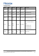
Change History Version Author Reviewer Approver Update Li Chen Jin Haibo 2022-10-27 Zhao V1.1.3 Add MC610-EU-07 and MC610- Meiqing V1.1.2 Gao Qiuqi Description LA-06 Li Chen Jin Haibo 2022-06-30 Add MC610-EU-05 Li Chen Jin Haibo 2022-03-03 Add MC610-EU-03 Jin Haibo 2021-10-28 Add B20 index and psm. Zhao V1.1.1 Meiqing Xu Wang Kaiqiang Liuxia V1.1.0 Modify voltage range and RF index, add WIFI-SCAN /BT Xu Wang V1.0.1 index.
Contents 1 2 3 About This Document ...................................................................................................8 1.1 Description ....................................................................................................................... 8 1.2 Safety Instructions ........................................................................................................... 8 1.3 References .................................................................................
3.5.3 USIM Design Requirements ............................................................................................... 39 3.6 UART Interface .............................................................................................................. 39 3.6.1 UART Interface Definition ................................................................................................... 39 3.6.2 UART Interface Application ...............................................................................
6 7 5.3 Electrical Characteristics of Interface Working State ...................................................... 61 5.4 Environment and Reliability Requirements ..................................................................... 61 5.5 ESD Characterization .................................................................................................... 62 Structural Specification ..............................................................................................63 6.
1 About This Document 1.1 Description This document describes information on electrical characteristics, RF performance, structural dimension, application environment, etc. of the MC610 series wireless module. With the help of this document and other related documents, the application developer can quickly understand the hardware functions of MC610 series modules and develop the hardware of the product. 1.
The mobile terminal equipment does not guarantee effective connection under any circumstances, for example, when the mobile terminal equipment is defaulted or (U) SIM is invalid. In case of the above situations in an emergency, remember to use the emergency call, and make sure your device is turned on and in an area of sufficient signal strength. Your mobile terminal equipment will receive and transmit RF signals when it is turned on.
⚫ 3GPP TS 27.007 V10.0.8: AT command set for User Equipment (UE) ⚫ 3GPP TS 27.005 V10.0.1: Use of Data Terminal Equipment - Data Circuit terminating Equipment (DTE - DCE) interface for Short Message Service (SMS) and Cell Broadcast Service (CBS) 1.
2 Product Overview 2.1 Product Introduction MC610 series module is a kind of broadband wireless terminal product suitable for TDD-LTE/FDD-LTE multiple network systems and multiple bands.
LTE FDD Rel.13 DL/UL 10.3 Mbps (20M) /5.1 Mbps (10M) LTE TDD Rel.13 9.1Mbps DL/3.1Mbps UL GPRS 85.6Kbps DL/85.6Kbps UL Data transmission Power 3.4 V to 4.2 V (recommended value: 3.8 V) Normal operation: -30°C to +75°C Temperature Extended operation: -40°C to +85°C Storage: -40°C to +90°C Power Sleep mode: 2.2mA consumption Package: LCC 52PIN+LGA 76PIN Physical Dimensions: 24.2 mm × 26.2 mm × 2.1 mm characteristics Weight: about 2 g. Interface Antenna Antenna: main set ×1, WIFI-SCAN/BT ×1 USIM3.
2.3 Hardware Diagram Figure 2-1 shows the main hardware functions of MC610 series modules, including baseband and RF functions. The baseband section contains: ⚫ LTE controller ⚫ PMIC ⚫ UART, SIM, I2C, SPI, ADC, KEY, SPK, MIC, HEADMIC, HP and SDIO The RF part includes: ⚫ RF PA ⚫ RF filter ⚫ Antenna Figure 2-1 Hardware diagram Reproduction forbidden without Fibocom Wireless Inc. written authorization - All rights reserved.
2.4 Operating Mode Table 2-2 Operating mode Mode Description The module is registered on the network, in a standby mode, without data Idle transmission. The module is connected to the network, in a working state, with data transmission in Talk/Data the voice call. The RF part of the module does not work, only the baseband part works, which is Airplane equivalent to the function of ordinary MCU.
3 Application Interface 3.1 LCC+LGA Interface MC610 series modules are packaged with LCC 52PIN+LGA 76PIN, with 128 pins in total. 3.1.1 Pin Distribution Figure 3-1 Pin distribution (top perspective view) Reproduction forbidden without Fibocom Wireless Inc. written authorization - All rights reserved.
3.1.2 Pin Definition Table 3-1 Pin definition Pin Pin Name Voltage Reset Domain Value I/O Description 1 GND G - - Ground 2 GND G - - Ground 3 ANT_MAIN I/O - - Main set antenna 4 GND G - - Ground 5 GND G - - Ground 6 NC - - - - 7 GND G - - Ground 8 GND G - - Ground - VBAT_GSM power input (3.4 to 4.2 V) - VBAT_GSM power input (3.4 to 4.2 V) Vmax=4.2V 9 VBAT PI Vmin=3.4V Vnorm=3.8V Vmax=4.2V 10 VBAT PI Vmin=3.4V Vnorm=3.
Pin Pin Name Voltage Reset Domain Value I/O Description Support function GPIO31/SIM2_SRST/U1RTS 18 UART1_RX I 1.8V - Data receiving of module serial port 1 19 UART1_TX O 1.8V - Data transmission of module serial port 1 20 UART1_RTS O 1.8V - DTE request to transmit data Module clearing transmitting 21 UART1_CTS I 1.8V - It can be modified by software as a CPlog port. It is recommended to reserve test points GPIO26 22 GPIO I/O 1.8V/3.
Pin Pin Name Voltage Reset Domain Value I/O Description Vmin=3.4V Vnorm=5.0V 32 GND G - - Ground 33 HP_R O - - Earphone right channel signal output 34 HP_L O - - Earphone left channel signal output 35 SPK_P O - - Loudspeaker positive output 36 SPK_N O - - Loudspeaker negative output 37 EMERG_RST I VBAT - Module reset signal, low level valid 38 LPG O 1.8V L Module state representation 39 U2RXD I 1.
Pin Pin Name Voltage Reset Domain Value I/O Description Multiplexing function I2C_SDA0/GPIO17 KEYOUT0 53 KEY_OUT0 O 1.8V - KEYOUT cannot be used as a key function alone. Clock signal line of LCD SPI 54 LCD_CLK O 1.8V/3V* Multiplexing function LCD_CLK/GPIO2 55 GND G - - Ground I2C interface clock signal I2C_SCL0/GPIO16 56 I2C_SCL0 O 1.8V When using GPIO, GPIO16 can only be used for output. 57 GND G - - 58 LCD_SIO I/O 1.
Pin Pin Name Voltage Reset Domain Value I/O Description 66 GND G - - Ground 67 ISENSE I - - Charging current detection signal 68 GND G - - Ground 69 LCD_CS O 1.8V - LCD chip selection signal Multiplexing function LCD_CS/GPIO3 70 GND G - - Ground Key pad input 0 71 USB_BOOT/KEY_IN0 I 1.8V - USB_BOOT rise to be in the DL mode KEYIN cannot be used as a key alone. The battery voltage detection signal should Vmax=4.
Pin Pin Name Voltage Reset Domain Value I/O Description Data receiving of module serial port 3 77 U3RXD I 1.8V/3V* - Multiplexing function SD1_D2/GPIO27/U2CTS/U3RXD/SPI2DIO_0 Data transmission of module serial port 3 78 U3TXD O 1.8V/3V* - Multiplexing function SD1_D3/GPIO28/U2RTS/U3TXD/SPI2DI_1 SPI camera power down 79 CAM_PWDN O 1.8V - Multiplexing function CAM_PWDN/GPIO19/SDA1 SPI camera reference CLK 80 CAM_REFCLK O 1.
Pin Pin Name Voltage Reset Domain Value I/O Description 86 GND G - - 87 KEY_OUT3 O 1.8V - Ground KEYOUT3 KEYOUT cannot be used alone. Key pad input 3 88 KEY_IN3 I 1.8V KEYIN cannot be used alone. MIPICSI_DATA_P0, CAM MIPI data 0 positive terminal 89 CSI_D0P I/O 1.8V Multiplexing function CAM_SCK/CSI_D0P/GPIO23 MIPICSI_DATA_N0, CAM MIPI data 0 negative terminal 90 CSI_D0N I/O 1.
Pin Pin Name Voltage Reset Domain Value I/O Description RGB LED current source input 1 97 SINK1 I - - The OPEN version can configure the current size.Imax=54mA RGB LED current source input 2 98 SINK2 I - - The OPEN version can configure the current size.Imax=54mA 99 HEADMIC_P I - - Earphone MIC input positive 100 HEADMIC_N I - - Earphone MIC input negative Key pad input 4 101 KEY_IN4 I 1.8V - KEYIN cannot be used alone. Keep it floating if not used.
Pin Pin Name Voltage Reset Domain Value I/O Description 109 GND G - - 110 I/O 1.8V L Ground GPIO12 GPIO Support function JTAG_TDO/SD2_D3 Analog-to-digital converter interface 3 111 ADC3 I - 1k in series when in use 112 GND G - - 113 VBUS I 5V - Ground USB insertion detection Keep it floating if not used. Data receiving of module serial port 2 114 U2RXD I 1.8V Multiplexing function GPIO/U2RXD Data transmission of module serial port 2 115 U2TXD O 1.
Pin Pin Name Voltage Reset Domain Value I/O Description LCD_FMARK/GPIO/FLS1SIO3/U2TXD 125 GND G - - 126 GPIO I/O 1.8V L Ground GPIO14 Support function SCL2/GPIO GPIO15 127 GPIO I/O 1.8V L Support function SDA2/GPIO 128 GND G - - Ground Note: ⚫ Unused pins are keep floating,”*” mean in development. ⚫ A single KEYIN/OUT key cannot be used, and it needs to be used with KEYOUT/IN.
3.2 Power The power interface of MC610 series modules is shown in the following table: Table 3-2 Power supply Pin Name I/O Pin Description VBAT PI 9,10 Module system power supply, 3.4 V to 4.2 V, nominal value of 3.8 V VDD_IO PO 13 Voltage output, 1.8 V (80 mA) 1,2,4,5,7,8,32,42,43,44,45,46, 47,48,49,50,51,55,57,60,63,65, GND G Ground 66,68,70,86,102,107,109,112, 116,121,125,128 3.2.1 Power Supply MC610 series modules need to provide power supply through VBAT pins.
Table 3-3 VBAT capacitance Recommended Application Description Capacitance Low ESR capacitance is required to reduce the power fluctuation of the module during operation. 220uFx2, Stabilized capacitance LDO or DCDC power supply requirements 10uF, 22uF are not less than 440 uF capacitance. Battery power supply can be reduced to 100 uF-220 uF capacitance. Filter out the interference caused by clock 1uF, 100nF Digital signal noise and digital signal.
Note: It is suggested that customers should add TVS (recommended model: ESDH4V5P1/ESD5651N) to VBAT input to improve the surge protection capability of products. 3.2.2 1.8 V Output MC610 series modules output 1.8 V voltage through VDD_IO for the use of the internal digital circuit of the module. The voltage is the logic level voltage of the module, which can be used to indicate the module to start up, and can also be used for external small current circuit applications.
Average Current Parameter Scenario Condition (mA) IGSM-RMS GSM850 260 GSM900 260 DCS1800 PCL0 200 PCS1900 PCL0 200 GSM GPRS Data transfer GSM850; PCL=5; 1Rx/4Tx GPRS Data transfer GSM900; PCL=5; 1Rx/4Tx IGPRS-RMS CS4 500 GPRS GPRS Data transfer DCS1800; PCL=0; 1Rx/4Tx GPRS Data transfer PCS1900; PCL=0; 1Rx/4Tx ILTE-RMS 500 LTE FDD 450 450 LTE FDD Data transfer Band 1 @+23dBm 700 LTE FDD Data transfer Band 2 @+23dBm 700 LTE FDD Data transfer Band 3 @+23dBm 700 LTE FDD Data transfe
Note: The above results are laboratory test data, with a deviation of ±10%. 3.3 Control Signal MC610 series modules provide 2-channel control signals to start up/shut down and reset the module. The pin definition is defined as shown in the following table: Table 3-6 Control signal Pin Name I/O Pin Description EMERG_R When the module is working, provide RESET with a Tst (100 ms) low ST/ I 37, 123 level, and then rise, reset the module.
ESD9X5VL-2/TR) should be placed near the button for ESD protection. The reference circuit is shown in the following figure: Figure 3-5 Key startup reference circuit 3.3.1.2 Startup Sequence Figure 3-6 Startup sequence control chart Note: Before lowering PWRKEY pins, VBAT voltage must be stable. It is suggested that the interval from VBAT energization to PWRKEY pin lowering should not be less than 30 ms. Reproduction forbidden without Fibocom Wireless Inc. written authorization - All rights reserved.
3.3.1.3 Automatic Startup If the module needs to be powered on for automatic startup, PWRKEY pins can be directly connected to the ground. In this way, the module sleep power consumption will increase by 0.2mA, and the module can only be powered off directly. 3.3.
3.3.2.1 Shutdown Sequence Figure 3-7 Shutdown sequence control chart 3.3.3 Module Reset There are two reset methods for MC610 series modules: hardware reset and AT command reset. Table 3-8 Module reset mode Reset Mode Reset Method Hardware reset Provide EMERG_RST with a Tst (100 ms) low level, and then rise it. AT command reset AT+CFUN=15 3.3.3.1 Reset Circuit The reset reference circuit is shown in the following figure, which is similar to PWRKEY control circuit.
Figure 3-8 EMERG_RST reset OC/OD reference circuit Another reset control is shown in the following figure: Figure 3-9 EMERG_RST reset button reference circuit Reproduction forbidden without Fibocom Wireless Inc. written authorization - All rights reserved.
3.3.3.2 EMERG_RST Control Timing Sequence Figure 3-10 EMERG_RST control timing sequence Note: EMERG_RST is a sensitive signal. It is suggested to add a debounce capacitor near the module end, the recommended capacity is 10nF. PCB layout should be away from RF interference and proper surrounding with grounding lines should be made, and routes on PCB edge and surface layer should be avoided (avoid module reset caused by ESD). 3.4 USB Interface MC610 series modules support USB2.
Pin Name I/O Pin Description VBUS_IN/VBUS PI 31,113 USB insertion detection For more information about the USB Specification 2.0, visit http://www.usb.org/home. Note: Since the module supports USB 2.0 High-Speed, the equivalent capacitance of the TVS tube on the USB_DM/DP differential signal line is required to be less than 1 pF, and TVS with capacitance of 0.
Pin Name I/O Pin Description SIM1_DET I 27 Detect USIM/SIM card for Hot-swap SIM2_SIO I/O 15 USIM/SIM2 DATA SIM2_CLK O 16 USIM/SIM2 Clock Signal SIM2_RST O 17 USIM/SIM2 RESET Signal VSIM2 PO 95 USIM/SIM2 Power Note: Dual card functionality can only be implemented on baseline 1.4 3.5.2 USIM Interface Circuit 3.5.2.
VIO_1V8 Set to high level detection SIM card MODULE SIM_CONNECTOR 1 USIM_VDD 2 22R R2 USIM_RESET USIM_PRESENCE R4 22R USIM_CLK C5 C4 C3 C2 C1 33pF 33pF 33pF 33pF GND 10 3 RST GND 8 DET SIM POL 5 CLK VPP 6 DATA RV4 RV3 RV2 RV5 C6 33pF R7 0.1uF 47K RV1 22R R3 USIM_DATA VCC GND R6 9 4.
grounding in series. 3.5.3 USIM Design Requirements The circuit design of SIM card needs to comply with EMC standards and ESD requirements, and needs to improve the electromagnetic susceptibility to ensure that the SIM card can work stably. The following points should be strictly observed in the design: ⚫ The layout of SIM card slot should be close to the module as far as possible, and away from RF antenna, DCDC power supply, clock signal line and other strong interference sources.
debugging.
3.6.2 UART Interface Application The serial port level of MC610 series modules is 1.8 V by default. If the level of the customer host system is 3.3 V or others, it is necessary to add a level converter in the serial port connection between the module and the host. The following figure shows the design of reference circuit using level conversion chip: Figure 3-14 UART signal connection 1 Another level conversion circuit is shown in the following figure.
Note: The level conversion circuit is not suitable for applications with baud rate over 460 Kbps. 3.7 Status Indication 3.7.1 LPG Signal MC610 series modules provide an interface of network indicator output signal. Table 3-15 LPG pin Pin Name I/O Pin Description LPG O 38 Module status indication Description of LPG status of MC610 series module network indicator.
Figure 3-16 Reference design diagram of network indicator for MC610 series modules 3.8 Low Power Mode 3.8.1 Sleep Mode The sleep mode can be activated by module by the following ways: 1. The ATS24 command makes the module to sleep, and the wake-up keeping time depends on in the command ATS24 = []. Send the AT command: ATS24=2. The module will enter the Sleep mode in 2 s, and the setting will not be saved after the module is powered down. 2. Set the sleep mode through AT+GTSET="LPMMODE".
3.8.2 Instructions for Module Sleep and Wakeup MC610 modules provide a KEYINT for module wakeup. When the module is in the sleep mode, lower or rise the WAKEUP_IN pin to wake up the module. If the wakeup module function is disabled, the WAKEUP_IN pin is suspended. Table3-17 WAKEUP_IN pins Pin Name I/O Pin Description WAKEUP_IN I 41 External device wakes up module signal 1. The block is not in the sleep mode by default. A non-0 value must be set by the ATS24 command, and then the module can sleep.
The following is the ADC precision tested on ADP-MC610-LA: Table 3-19 ADC precision Voltage Range (V) Precision (mV) 0-1.1 3 1.2-3.3 40 3.3-VBAT 10 Note: In case of higher requirements for precision, it is recommended to use a lower voltage range. It is recommended that the ADC should be surrounded with grounding lines, so as to improve the precision of ADC voltage measurement; When using the ADC, a 1 K resistor must be connected in series. 3.
SPK output power: 800 mW @ 4.2 V on 8 Ω load in Class-D mode, 600 mW @ 4.2 V on 8 Ω load in Class-AB mode. The default power amplifier of the module is Class-AB output. When an external power amplifier is required, the recommended model is: AW87359FCR (2 W @ 8 Ω). 3.10.1.1 SPK Interface Circuit Figure 3-17 Reference circuit of SPK output Figure 3-18 Reference circuit of Audio Power Amplifier Output Reproduction forbidden without Fibocom Wireless Inc. written authorization - All rights reserved.
3.10.2 HP Headphone Jack Table 3-17 HP pins HP_R O 33 Earphone right channel signal HP_L O 34 Earphone left channel signal Module earphone output power: 25 mW @ ± 1.8 V on 32 Ohm load, gain range: -18 dB to + 0 dB with 3 dB steps (4-bit programmable gain). 3.10.
Figure 3-19 MIC reference circuit HEADMIC_P/N also requires an external offset. Figure 3-20 The headset MIC reference circuit 3.10.4 Preventing TDD and Other Noises Handheld microphones and hands-free microphones are recommended to adopt built-in RF filter dualcapacitance (such as 10 pF and 33 pF) electret microphones to filter out RF interference from the source Reproduction forbidden without Fibocom Wireless Inc. written authorization - All rights reserved.
of interference, which will greatly improve the coupling TDD noise. 33 pF capacitor is used to filter high frequency interference when the module is working at 900 MHz, and 10 pF capacitor is used to filter high frequency interference when working at 1,800 MHz. If the capacitor is not added, TDD noise may be heard during a call.
Pin name I/O Pin CSI_D0P I/O 89 Description CAMERA MIPI data D0 positive terminal; CAM_SCK SPI CAM serial clock signal CAMERA MIPI clock CLK negative terminal; CSI_CKN O 92 CAM_RSTL SPI CAM reset signal CAMERA MIPI clock CLK positive terminal; CSI_CKP O 91 CAM_SI0 SPI CAM serial data signal 0 I2C_SDA0 I/O 52 CAMERA I2C data signal I2C_SCL0 O 56 CAMERA I2C clock signal Note: For the detailed design of CAMERA, see the latest MC610 Series Reference Design. 3.
Note: ⚫ LCDpin is defined in the above table as the reuse function of the standard version, which needs to be configured in OPEN ⚫ For the detailed design of LCD, see the latest MC610 Series Reference Design. 3.13 USB_BOOT Interface Modules need to be in download mode to download. Pull USB_BOOT up to 1.8V, and the module will enter download mode when it is powered on again. In download mode, the module can be upgraded via the USB interface.
the corresponding key during power-on will cause the module to enter download mode because KEYOUT has a high pulse output during power-on. 3. USB_BOOT should add 1K resistor and TVS tube near module end, Improve esd prevention capabilities. Reproduction forbidden without Fibocom Wireless Inc. written authorization - All rights reserved.
4 RF Interface 4.
LTE FDD LTE TDD PCS 1900 30±2 - Band 1 23±2 10MHz Bandwidth, 1 RB Band 2 23±2 10MHz Bandwidth, 1 RB Band 3 23±2 10MHz Bandwidth, 1 RB Band 4 23±2 10MHz Bandwidth, 1 RB Band 5 23±2 10MHz Bandwidth, 1 RB Band 7 23±2 10MHz Bandwidth, 1 RB Band 8 23±2 10MHz Bandwidth, 1 RB Band 20 23±2 10MHz Bandwidth, 1 RB Band 28 23±2 10MHz Bandwidth, 1 RB Band 66 23±2 10MHz Bandwidth, 1 RB Band 38 23±2 10MHz Bandwidth, 1 RB Band 40 23±2 10MHz Bandwidth, 1 RB Band 41 23±2 10MHz Bandw
LTE TDD Band 28 -98 10MHz Band width Band 66 -98 10MHz Band width Band 38 -97.5 10MHz Band width Band 40 -97.5 10MHz Band width Band 41 -97.5 10MHz Band width 4.4 WIFI-SCAN/BT WIFI-SCAN/BT receiving sensitivity is shown in the following table: Function Mode Rx Sensitivity (dBm) Note WIFI-SCAN 11b -90 PER<8% BT Basic-DH1 -88 BER<0.1% BT EDR-2-DH1 -88 BER<0.01% BT EDR-3-DH1 -80 BER<0.01% BT BLE -91 PER<30.
4.5 RF PCB Design 4.5.1 Antenna RF Connector The antenna of the MC610 series modules is led from bonding pads. It is recommended that customers use the U.FL-R-SMT-1 antenna connector and use the matching RF adapter lines. The antenna is a sensitive device and is easily affected by the external environment. For example, the position of the antenna, the occupied space, and the surrounding grounding may affect the performance of the antenna.
the antenna. ⚫ It is recommended to use intact formations as reference ground. ⚫ The ground around the antenna strengthens the connection with the main ground. Note: Refer to FIBOCOM Design Guide_RF Antenna for detailed design. 4.6 Antenna Design 1. Antenna Requirements Antenna efficiency is the ratio of antenna input power to radiation power.
The recommended antenna gain is ≤ 2.5 dBi 6. Interference In addition to the antenna performance, other interference on the PCB board will also affect the module performance. In order to ensure the high performance of the module, the interference must be well controlled. Suggestions: for example, LCD, CP, FPC wiring, audio circuit, power supply part should be as far away from the antenna as possible, and the corresponding isolation and shielding, or filtering processing should be made on the path.
Main Antenna Requirements of MC610 Series Module Impedance 50Ω > 33 dbm (2 W) peak power GSM Input power > 23 dbm average power LTE Standing wave ratio ≤ 2:1 recommendation Reproduction forbidden without Fibocom Wireless Inc. written authorization - All rights reserved.
5 Electrical Characteristics 5.1 Limiting Voltage Range The limiting voltage range refers to the maximum voltage range that the module power supply voltage and digital and analog I/O interfaces can withstand. The voltage range of MC610 series module is shown in the table below. Table 5-1 Limiting voltage Parameter Description Min Typ Max Unit VBAT Power supply -0.3 - 4.5 V GPIO Level supply voltage of digital I/O -0.3 - 2.0/3.2V V 5.
5.3 Electrical Characteristics of Interface Working State VL: logic low level; VH: logic high level; Table 5-3 IO Interface level VL Level VH Signal 1.8 V 3V Unit Min Max Min Max Digital input I - 0.54 1.26 2.0 V Digital output O - 0.36 1.44 - V Digital input I - 0.45 2.1 3.2 V Digital output O - 0.45 2.1 - V Table 5-4 Power Interface level Parameter I/O Min Typ Max Unit VBAT I 3.4 3.8 4.2 V SIM_VCC O 1.7/2.75 1.8/2.85 1.9/2.95 V 5.
Test Item Test Condition High temperature and humidity The temperature is +65°C ± 3°C, the humidity is 90 to 95% RH, test and the Power OFF state lasts for 88 hours The temperature Is -30°C ± 3°C, and the working condition lasts Low-temperature running test for 24 hours The temperature is +75°C ± 3°C, and the working condition lasts High-temperature running test for 24 hours Random vibration ASD (acceleration Frequency spectral density) Vibration test Test for connector lifetime 5 to 20Hz 0.
6 Structural Specification 6.1 Product Appearance The appearance of MC610 series modules is shown in the figure: Figure 6-1 Module product appearance (top) Figure 6-2 Module product appearance (bottom) Reproduction forbidden without Fibocom Wireless Inc. written authorization - All rights reserved.
6.2 Structure Size The structure size of MC610 series modules is shown in the following figure: Figure 6-3 Structural dimension drawing (unit: mm) 6.3 SMT Paster ⚫ Please refer to FIBOCOM MC610 Series SMT Design Guide for module steel mesh design, solder paste and furnace temperature control. 6.
7 Warning 7.1 FCC warning OEM/Integrators Installation Manual Important Notice to OEM integrators 1. This module is limited to OEM installation ONLY. 2. This module is limited to installation in mobile or fixed applications, according to Part 2.1091(b). 3. The separate approval is required for all other operating configurations, including portable configurations with respect to Part 2.1093 and different antenna configurations. 4. For FCC Part 15.
Antenna (1) The antenna must be installed such that 20 cm is maintained between the antenna and users, (2) The transmitter module may not be co-located with any other transmitter or antenna. In the event that these conditions cannot be met (for example certain laptop configurations or colocation with another transmitter), then the FCC authorization is no longer considered valid, and the FCC ID cannot be used on the final product.
Federal Communication Commission Interference Statement This device complies with Part 15 of the FCC Rules. Operation is subject to the following two conditions: (1) This device may not cause harmful interference, and (2) this device must accept any interference received, including interference that may cause undesired operation. This equipment has been tested and found to comply with the limits for a Class B digital device, pursuant to Part 15 of the FCC Rules.
This device is intended only for OEM integrators under the following conditions: (For module device use) 1) The antenna must be installed such that 20 cm is maintained between the antenna and users, and 2) The transmitter module may not be co-located with any other transmitter or antenna. As long as 2 conditions above are met, further transmitter test will not be required.
8 Appendixes 8.
Abbreviation Description SMS Short Message Service TDMA Time Division Multiple Access TE Terminal Equipment TX Transmitting Direction TDD Time Division Duplexing UART Universal Asynchronous Receiver & Transmitter UMTS Universal Mobile Telecommunications System URC Unsolicited Result Code (U)SIM (Universal) Subscriber Identity Module USSD Unstructured Supplementary Service Data Vmax Maximum Voltage Value Vnorm Normal Voltage Value Vmin Minimum Voltage Value VIHmax Maximum Input H
Abbreviation Description VSWR Voltage Standing Wave Ratio WCDMA Wideband Code Division Multiple Access 8.2 Contact Company website: http://www.fibocom.com.cn/ Tel: +86 755-26733555 Fax: +86 755-26520841 Reproduction forbidden without Fibocom Wireless Inc. written authorization - All rights reserved.