
Hardware Guide

4 Circuit Design
Copyright © Fibocom Wireless Inc. 51
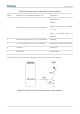
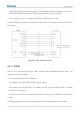
4.4.6.4 (U)SIM Card Design Requirements
(U)SIM circuit design must meet EMC standards and ESD requirements, and at the same
time, EMS capability must be improved to ensure that the SIM can work stably. The
following principles must be strictly followed in the design:
(U)SIM card connector should be located as close to the module as possible, and kept
away from the RF antenna, DCDC power, clock signal cables and other strong
interference sources.
SIM card connector is covered by metal shield shell to improve EMS.
The cabling length from the module to the SIM card connector shall not exceed
100mm. Longer cable will reduce signal quality;
USIM_CLK and USIM_DATA signal lines are grounded and isolated to avoid mutual
interference. If it is difficult to do so, at least (U)SIM card signals must be wrapped with
copper connected to the ground.
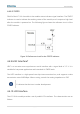
The filter capacitor and ESD device of the (U)SIM card signal line are placed close to
the (U)SIM card slot. The upper limit of the equivalent capacitance of the ESD device is
22-33 pF.
It is recommended to make a clearance design for the PCB directly under the
shrapnel of the SIM card connector to avoid the insulating green oil on the surface of
the PCB being worn down when the shrapnel is pressed down, resulting in a short
circuit between the SIM card signal line and the ground.
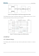
USIM_DATA is pulled up to USIM_VDD via a 10 kΩ resistor.
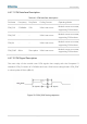
4.4.7 PCM
The LC116-LA module provides a digital audio interface PCM for communication with
external codec and other digital audio devices.