
Hardware Guide

4 Circuit Design
Copyright © Fibocom Wireless Inc. 47
peripherals with high real-time requirements, please do not share I
2
C with other
peripherals.
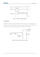
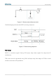
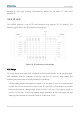
4.4.4 SD card
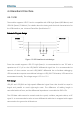
The module supports a set of SD card interfaces that support SD 3.0 protocol. The
following figure shows the SD reference circuit design.
Figure 16. SD reference circuit design
PCB Design
SD circuit design must meet EMC standards and ESD requirements, and at the same time,
EMS capability must be improved to ensure that the SD card can work stably. The
following principles must be strictly followed in the design:
If the cabling length of signal lines is equal to or less than 50 mm. It is recommended
to place the SD card connector as close to the SD signal pins of the module as possible
because the internal cabling length of the module is 40 mm. If the cabling length is
equal to or less than 10 mm, the cabling length difference of the clock signal line and
data signal line should be controlled equal to or less than 1 mm.