
Hardware Guide

4 Circuit Design
Copyright © Fibocom Wireless Inc. 35
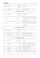
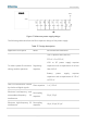
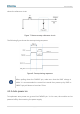
VBAT
Module
6.8pF
8.2pF
18pF
33pF
39pF
100nF
1uF
220uF
220uF
+ +
VBAT
Figure 5. Reference power supply design
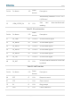
The following table describes the filter capacitor design of the power supply.
Table 37. Design description
Application Description
Mode
Recommended Parameter
To reduce power fluctuations
during module operation
Regulating
capacitor
Use a capacitor with low ESR;
220 uF x 2 or 330 uF;
LDO or DC power supply requires
capacitors with a capacitance of no less
than 440 uF.
Battery power supply requires
capacitors with a capacitance of 100 uF
to 220 uF.
Filter out interference caused
by clock and digital signals.
Filter capacitor
1 uF, 100 nF
Eliminate low-frequency and
intermediate-frequency RF
interference.
Decoupling
capacitor
39 pF, 33 pF
Eliminate high-frequency RF
interference.
Decoupling
capacitor
18 pF, 6.8 pF, 8.2 pF