User's Manual
Table Of Contents

H350 LGA Serials Module Hardware User Manual Page of
43
33
RI UART1_RI
DCD UART1_DCD
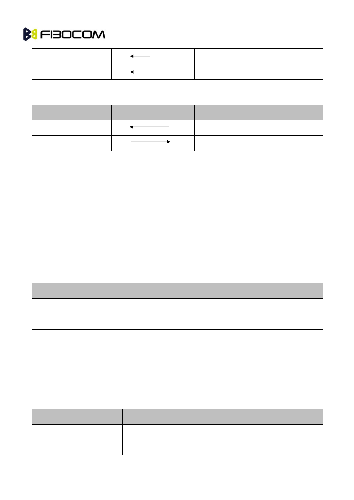
The following table shows the signal direction when H350 wireless communication module (DCE) UART2
connects to PC (DTE):
Application MCU(DTE) Signal Direction H350 Module (DCE)
RXD UART2_TXD
TXD UART2_RXD
Note: Module UART high level is 1.8V, please use external level shifter if connect to 2.8V or 3.3V IO
interface.
When you design:
Level shift from 1.8V to 3.3V, SN74LVC2G07 is recommended.
When UART1 communicating with PC, first translates from 1.8V to 3.3V, and then uses SP3238 to
translate.
When UART2 communicating with PC, first translates from 1.8V to 3.3V, and then uses SPIEX3232EEA
to translate level. Notice the signal direction when translate level.
5.5.3 Ring Indicator
UART1_R1 is used for indicating incoming call and SMS, sending pulse to host application program.
Operation Mode Status
Default mode Low level
Ringing 1s high level, 1s low level, cycling
Incoming message 150ms pulse
5.6 USIM
H350 wireless communication module supports USIM and high speed SIM card, does not support 8 line
smart USIM yet.
5.6.1 USIM Interface
Pin# Pin Name I/O Description
26 USIM_VCC O USIM power supply output
25 USIM_RST O USIM Reset signal


