
User Manual

2. Fitting
2−13
Festo P.BE−SPC200−EN en 0901d
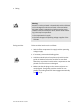
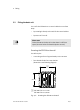
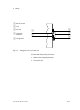
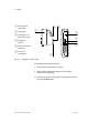
1 Control panel
(side view)
2 Locking pin
3 Locking pins on
the control panel
4 Diagnostic
module
5 Socket for control
panel (X3)
6 Groove for
locking pins
1
23
4
5
6
2
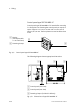
Fig.2/4: Fitting the control panel
Proceed with dismantling as follows:
1. Switch off the compressed air supply.
2. Switch off the operating voltage and load voltage
supplies for the SPC200.
3. Carefully lift up the control panel from diagnostic module
type SPC200−MMI−DIAG.