
User Manual

2. Fitting
2−12
Festo P.BE−S PC200−EN en 0901d
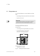
2.3 Fit the control panel into position
Control panel type SPC200−MMI−1
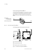
Control panel type SPC200−MMI−1 can be inserted directly
into the diagnostic module type SPC200−MMI−DIAG of the
SPC200 (see Fig.2/4).
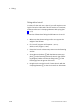
Warning
Actuators can be activated unintentionally and the SPC200
can be damaged if modules are fitted or removed when
the power supply is switched on. Before carrying out in
stallation and/or maintenance work, switch off the follow
ing in the sequence specified:
1. the compressed air supply
2. the load and operating voltage supplies on the
SPC200
and, if applicable, the load voltage supply on the axis
interface string.
Proceed with fitting as follows:
Control panel type SPC200−MMI−1 can be inserted directly
into the diagnostic module type SPC200−MMI−DIAG of the
SPC200 (see Fig.2/4).
1. Switch off the compressed air supply.
2. Switch off the load voltage and operating voltage sup
plies on the
SPC200.
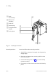
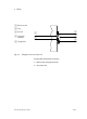
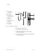
3. Carefully place the control panel onto the diagnostic
module type SPC200−MMI−DIAG of the SPC200. Make
sure that plug 3 and socket 5 are correctly aligned be
fore fully inserting the control panel.
4. Make sure that locking pins 2 snap into position.