
User Manual

2. Fitting
2−6
Festo P.BE−S PC200−EN en 0901d
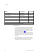
Module Type designation Max. number
Power supply module SPC200−PWR−AIF 1
Diagnostic module SPC200−MMI−DIAG 1
Sub−controller module SPC200−SCU−AIF 1
Field bus module SPC200−COM−... 1
Nominal value module SPC200−2AI−U 2
Stepping motor indexer modules SPC200−SMX 3
I/O modules SPC200−DIO 3 or 4
1)
1)
Maximum four I/O modules if a field bus module is not installed.
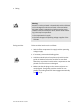
Recommendation:
If a sub−controller or stepping motor module is installed.
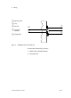
Check to see if the modules must be fitted in a certain
sequence. Axis identifiers (X...U) are assigned automati
cally to these modules in ascending order without gaps
from left to right (see chapter 1.3).
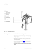
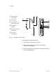
Mount the sub−controller module if possible in the outer
most right−hand location. The cable screening/shield can
then be fitted easily to the earth connection on the right−
hand side.
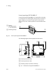
Mount the stepping motor indexer module and the field
bus module with a gap of at least one location from the
diagnostic module, if you are using a control panel.