
User Manual

2. Fitting
2−5
Festo P.BE−SPC200−EN en 0901d
2.1 Fitting and removing components
Caution
Components may be damaged if they are not handled
correctly.
· Do not touch the electrical contacts of the modules.
· Observe the regulations for handling electrostatically
sensitive components.
· Protecting the components against discharges of static
electricity: Discharge yourself of static electricity before
fitting or removing the modules.
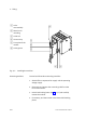
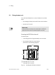
The rack type SPC200−CPU−... serves as a housing for the
components of the SPC200. The processor and memory of
the SPC200 are situated on the integrated rear−wall printed
circuit board. The components inserted are connected
with
each other via this rear−wall printed circuit board.
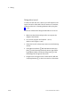
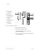
The components are fastened with the aid of a locking lever
on the rack. A tool is not therefore required for fitting or re
moving the components.
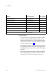
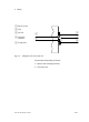
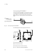
Locations The locations are marked from left to right with 1 to 4 or 6.
Location 1 is
reserved for the power supply module
(typeSPC−200−PWR−AIF). Other components can be fitted as
desired in locations 2 to 4 or 6. Individual identification of all
inserted components is carried out automatically.