
User Manual

1. Summary of components
1−22
Festo P.BE−S PC200−EN en 0901d
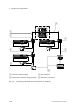
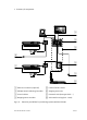
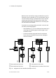
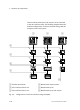
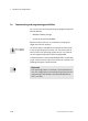
Further modules with inputs and outputs can be connected
to the axis interface string. The following diagram shows the
possible configurations on the axis interface string, with the
example of a two−axis system.
POWER
ERROR
OUT
VALV E
IN
POWER
DIAG
OUTPUT
PNP
01
INPUT/OUTPUT
INPUT01
POWER
ERROR
OUT
VALV E
IN
POWER
ERROR
OUT
VALV E
IN
POWER
ERROR
OUT
VALV E
IN
POWER
ERROR
OUT
VALV E
IN
POWER
ERROR
OUT
VALV E
IN
11 1
2
3
4
5
6
1
Possible alternatives
2 Axis interface of the X−axis
3 Axis interface of the Y−axis
4 Module with outputs/valves
5 Module with inputs
6 Module with inputs and outputs
Fig.1/9: Configurations on the axis interface string (examples)