
User Manual

A. Notes on installing the pneumatic components
A−35
Festo P.BE−SPC200−EN en 0901d
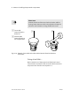
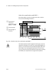
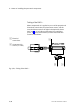
Installation instructions for standard cylinder
typeDNCI−...
Any mounting position is permitted (horizontal, vertical or
diagonal)
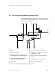
· Note that in conjunction with the SPC200, the complete
stroke of the drive must not be used.
Permitted work stroke = stroke length minus stroke
reduction
On each side of the drive positioning must not take place in
the range of the stroke reduction (see also chapter 3.4).
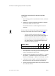
The best possible positioning behaviour can
be
achieved if you use only 80 % of the stroke length of
the drive, symmetrically to the two end positions.
If demands placed on the positioning behaviour are
only slight, observe at least the following stroke re
ductions in both end positions:
Piston j [mm]
32 40 50 63
Stroke reduction per end position [mm] 10 10 15 15
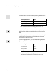
· Recommendation: Limit the movement range by means of
shock absorbers. In this way you can avoid damage in the
event of operating and system faults.
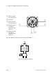
· Arrange the tubing between the valve (MPYE−5−...) and the
drive (DNCI−...) symmetrically and as short as possible.
Maximum tubing length = cylinder stroke length + 50 mm.
· Lubricate the external guide at suitable maintenance in
tervals (be sure to note manufacturer specifications).
· Use only fastening elements which can permanently resist
the acceleration forces.