1. Summary of components
1−18
Festo P.BE−S PC200−EN en 0901d
POWER
DIAG
OUTPUT
PNP
01
INPUT/OUTPUT
INPUT
01
1
2
3
4
3
3
1
2
1
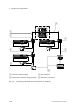
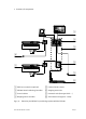
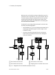
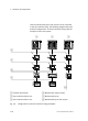
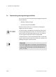
First axis interface string
2 Second axis interface string (optional)
3 Axis interface
4 External I/O modules
Fig.1/5: Connecting pneumatic axes and external I/O modules