
User Manual

A. Notes on installing the pneumatic components
A−14
Festo P.BE−SPC200−EN en 0901d
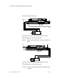
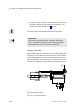
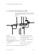
· Arrange the tubing between the valve (MPYE−5−...) and the
drive (DNC−...) symmetrically and as short as possible.
Maximum tubing length Ţ Cylinder stroke length + 50 mm.
· Lubricate the external guide at suitable maintenance
intervals (note manufacturer specifications).
· Use only fastening elements which can permanently resist
the acceleration forces.
Recommendation: Use the following fastening elements from
Festo:
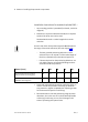
Fastening elements
Type
Base fastening HNC−...
Flange fastening FNC−...
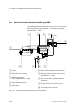
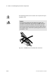
· Use a suitable guide for absorbing lateral forces.
The cylinder, guide, measuring system and load must be rigid
in the direction of movement, have very little play and must
be connected flush with each other.
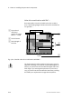
In positioning applications, use only the following elements
approved by Festo for coupling the mass load to the
drive:
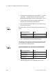
Connecting element
Type
Articulated head SGS−...
Swivel journal kit ZNCM−...
Bearing block LNZG−...
· Check the play of the coupling.
The following applies here: Coupling play Ţ 0.05 mm