
User Manual


A. Notes on installing the pneumatic components
A−5
Festo P.BE−SPC200−EN en 0901d
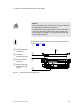
Installation instructions for drives DGP(L)−... and
DG PI(L)−...
Any mounting position is permitted (horizontal, vertical or
diagonal)
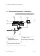
· Note that in conjunction with the SPC200, the complete
stroke of the drive must not be used.
Permitted work stroke = stroke length minus stroke
reduction
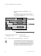
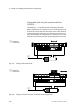
1 Permitted work
stroke = (stroke
length minus
stroke reduction)
2 Stroke reduction
1
2
Fig.A/3: Permitted working stroke
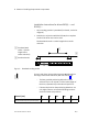
On each side of the drive positioning must not take place in
the range of the stroke reduction (see also section 3.4).
The best possible positioning behaviour can be
achieved if you use only 80 % of the stroke length of
the drive, symmetrically to the two end positions.
If demands
placed on the positioning behaviour are
only slight, observe at least the following stroke re
ductions in both end positions:
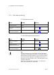
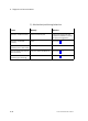
Pistonj [mm]
25 32 40 50 63
Stroke reductionper end position [mm] 25 25 35 35 35