
User Manual


8. Diagnosis and error treatment
8−4
Festo P.BE−S PC200−EN en 0901d
8.1 On−the−spot diagnosis
The LEDs on the power supply module, the axis interface and
the I/O modules (optional) supply information on the operat
ing status of the system. The tables below show how the vari
ous operating states are represented by the LEDs. The LEDs
indicate the following:
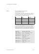
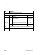
LED
Meaning
LED lights up
LED out
LED flashes
permanently without break
or
several times with a break (flashing sequence
corresponds to fault class which has occurred
with a 1−second break, see also section 8.2)
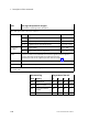
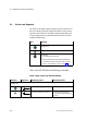
LED on the SPC200 Smart Positioning Controller
Power supply module type SPC200−PWR−AIF
Reaction
Sequence Operating status Eliminating faults
POWER LED
ON
OFF
Operating voltage applied None
ON
OFF
Operating voltage not applied · Check operating voltage
connection of the electronics
(pin 2).