
User Manual

7. Description of the commands
7−68
Festo P.BE−S PC200−EN en 0901d
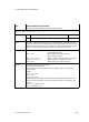
M10
Activate the nominal value input
permitted in operating modes: Start/Stop
Nn M10 X<Factor> [Y.., Z.., U..]
<Factor> n
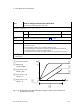
Scaling factor in [mm/V] or [°/V] (see Fig.7/18) n = 0.1 ... 9999.9
No specification of a scaling factor
1)
@n
Scaling factor saved in position register @n
2)
n = 0 ... 99
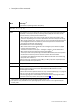
Effect The effect of command M10 depends on the syntax.
Without specification of a scaling factor (e.g. M10 X"):
All settings undertaken with M10, M11, M13 or M14 will be reset to the confi
gured standard values (parameter set for the axis, register card Nominal value
specification"). The input for the direct nominal value
specification will be acti
vated with the configured standard values.
With specification of a scaling factor (e.g. M10 X200.5"):
The input for analogue nominal value specification is activated with the specified
scaling factor. Settings for offset, mode or analogue channel assignment defined
with the commands M11, M13 and M14 are valid. Otherwise the
configured
standard settings are used. With the scaling factor, you can specify the position
ing path which is to be covered by the analogue nominal value specification
(0...10V) (e.g. factor = 20, possible positioning path = 200mm).
The scaling factor has no effect with the digital setpoint value specification
(input 5). In this
case, the setpoint values are absolute position values that refer
to the project zero point.
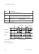
PROFIBUS: The setpoint values are specified by the PLC in m.
(Example: Target position 88.24 mm −> output data of the PLC
= 882400 presented as decimal)
DeviceNET: The setpoint values are specified by the PLC in m.
Example See following pages
Remark The reference point of the positioning range is the project zero point.
By specifying the offset (command M11") you can shift the reference point
(see Fig.7/18).
With modes 0 and 1 (see command M13), the analogue input must be deacti
vated with M12 before it can be activated again with M10. The
command G25
has no effect in these modes.
With stepping motor axes: modes 0 and 1 are not supported.
1)
This syntax is only available as from operating system version 4. The value 0000.00 is
represented or entered on the control panel.
2)
This syntax is only available as from operating system version 4.82. It is not supported by the
control panel.