
User Manual

6. Operating the SPC200 with the control panel
6−20
Festo P.BE−S PC200−EN en 0901d
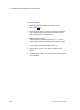
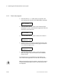
Reference points With the following four parameters you can specify the
reference points of your positioning system.
Note that the software end positions and the project zero
point refer to the cylinder zero point. If you modify the
mounting offset, the SPC200 will check to see if the resulting
new reference points still lie
within the range of the measur
ing system. If this is not the case, an appropriate fault mess
age will be displayed.
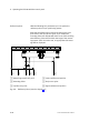
12 3
4
5
6
1 Measuring system zero point
2 Mounting offset
3 Cylinder zero point
4 Lower software end position
5 Project zero point
6 Upper software end position
Fig.6/8: Reference points (see also chapter 3.4)