
User Manual

5. Controlling the SPC200
5−22
Festo P.BE−S PC200−EN en 0901d
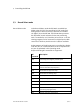
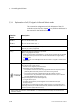
5.3.1 Explanation of all I/O signals in Record Select mode
The connection assignment and I/O addresses of the I/O
modules can be found in chapter 3.5.4, field bus addresses in
the manual for the field bus module.
Function
Inputs
Description
RECBIT1
...
RECBIT5
Bit 1 for record number (2
0
)
...
Bit 5 for record number (2
4
)
1)
CLK_B Start NC record from program B or quit fault
(like CLK_A, but for program B)
CLK_A Start NC record from program A or quit fault
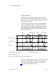
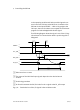
With a rising edge at this input:
the NC record number at the RECBIT... inputs will be accepted by the SPC200
for program A and processed. This will be indicated with the signal ACK_A
(see Fig.5/8).
an active fault is acknowledged if at the
same time a 1−signal is active at the
STOP input.
STOP Stop positioning task
An 0−signal at this input causes:
the axes to be stopped (controlled stop).
Depending on the parameterisation:
The position at the time of the stop signal becomes the setpoint position
(default). After standstill, the axis runs back to this
p
osition.
New feature a
s
from OS 4.93
(default)
.
After
standstill
,
the
axis
runs
back
to
this
position
.
The current position at standstill becomes the setpoint position.
This function is only available as from firmware version 4.93 in combina
tion with WinPISA as from version 4.51.
The positioning task can be started again by:
a 1−signal at this input
renewed starting of the positioning task via the relevant CLK input
(CLK_A/CLK_B).
Continuation
of a positioning task after a Stop signal is not supported in this
operating mode. If you use NC command G91, movement must be made to an
absolute position (G90) after each stop.
1)
With control via a field bus module RECBIT... as 2−byte value from 0 to 999, see manual on the
field bus module.