
User Manual

5. Controlling the SPC200
5−18
Festo P.BE−S PC200−EN en 0901d
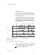
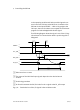
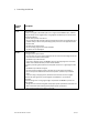
The following diagram shows an example of an I/O circuit for
Record Select mode.
0V
24V
9 8 7 24V 0/4 5/6
I0.9 I0.8 I0.7 I0.0/I0.4 I0.5/I0.6
ENABLE R ESET
1)
STOP RECBIT... CLK_B/A
24V
1
2
3
Outputs
Inputs
PLC/IPC
24V
24V
0V
0V
3/4 5/6 7
_
Q0.3/Q0.4 Q0.5/Q0.6 Q0.7
RC_B/A ACK_B/A READY
4
5
6
7
4
_
_
1 Designation on plug X5
2 Input address (I = input)
3 Function
4 Load voltage (can be switched off
separately)
5 Designation on plug X6
6 Output address (Q = output)
7 Function
1)
RESET (program reset) in conjunction
with a 0−signal at the STOP input
Fig.5/7: Example of an I/O circuit for the operating mode Record Select with two
starting programs