
User Manual

5. Controlling the SPC200
5−11
Festo P.BE−SPC200−EN en 0901d
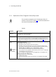
5.2.1 Explanation of all I/O signals in Start/Stop mode
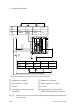
The connection assignment and I/O addresses of the I/O
modules can be found in chapter 3.5.3, field bus addresses in
the manual for the field bus module.
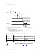
Inputs
Function Description
SYNC_IB Synchronization input for program B
(like SYNC_IA, but for program B)
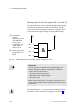
SYNC_IA Synchronization input for program A
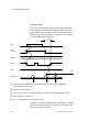
This input supports synchronization of the SPC200 with external devices (e.g.
PLC/IPC). With a Programmed Stop (command M00) the SPC200 waits for a fal
ling edge at this input before it processes the next NC record (see Fig.5/6).
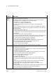
STOP Stop program sequence
A falling edge at this input causes:
the program sequence and the axes to be stopped.
Depending on the parameterisation, the axis is stopped (controlled stop):
The position at the time of the stop signal becomes the setpoint position
(d f lt) Aft t d till th i b k t thi iti
New feature
as from
OS 4.93
(default). After standstill, the axis runs back to this position.
The current position at standstill becomes the setpoint position.
This function is only available as from firmware version 4.93 in combination
with WinPISA as from version 4.51.
If there is a 0−signal, a Program Reset can be triggered by a rising edge at
the
START input (see under ST ART input).
The program sequence is continued by:
1. a 1−signal at this input
2. a new start signal (Start on the control panel or a rising edge at the START
input).